

Electronic apparatus and vibrating method
a technology of electronic equipment and vibrating method, which is applied in the direction of adaptive control, instruments, and tactile signalling systems, etc., can solve the problems of difficulty in perceiving the frequency vibration type, inability to allocate individual vibrations to multiple types of notification events, and difficulty for users to perceive differences
- Summary
- Abstract
- Description
- Claims
- Application Information
AI Technical Summary
Benefits of technology
Problems solved by technology
Method used
Image

Examples
first embodiment
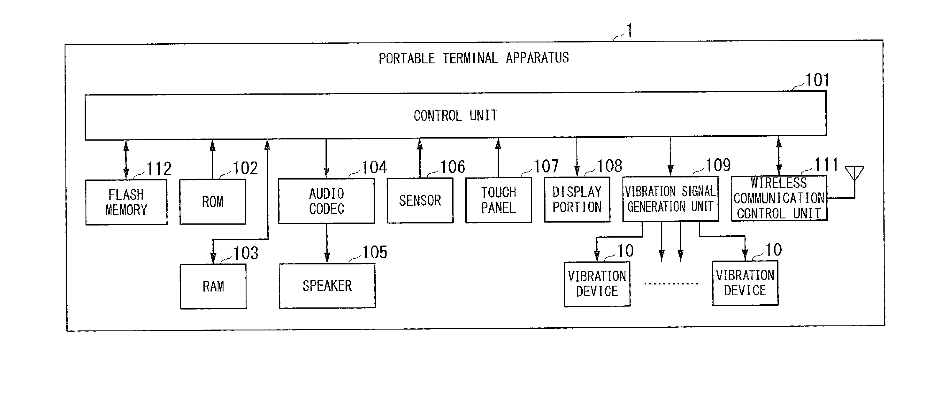
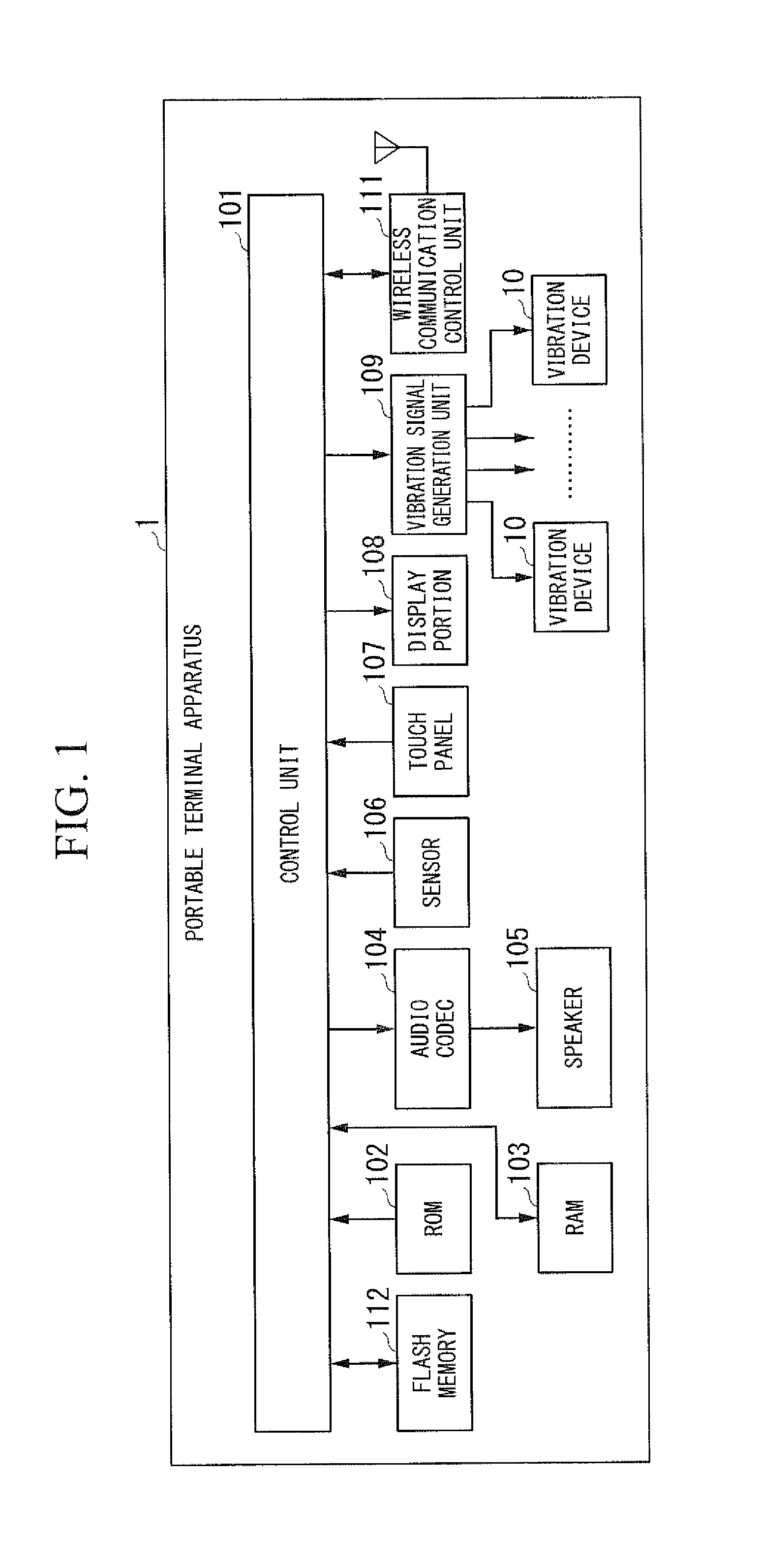
[0029]FIG. 1 is a block diagram illustrating a configuration of a portable terminal apparatus 1 according to the present embodiment,
[0030]The portable terminal apparatus 1 is, for example, an electronic apparatus such as a cellular phone, a PDA (Personal Digital Assistant), a smart phone, a game console, and a digital camera. As shown in the drawing, the portable terminal apparatus 1 is configured to include a control unit 101, a ROM (Read Only Memory) 102, a RAM (Random Access Memory) 103, an audio codec 104, a speaker 105, a sensor 106, a touch panel 107, a display portion 108, a vibration signal generation unit 109, a plurality of vibration devices 10, a wireless communication control unit 111, and a flash memory 112.
[0031]The control unit 101 is a CPU (Central Processing Unit) and a peripheral interface, and controls the portable terminal apparatus 1 as a whole. The control unit 101 independently controls the frequencies or strengths of vibrations generated by a plurality of vib...
second embodiment
[0080]Next, the portable terminal apparatus 1 according to a second embodiment of the present invention will be described.
[0081]The control unit 101 according to the present embodiment vibrates two or more vibration devices 10 simultaneously, and changes the ratio of the strength of a vibration generated by each of the vibration devices 10 together with the time. Other configurations are the same as those of the portable terminal apparatus 1 according to the first embodiment, and thus the description thereof will be omitted.
[0082]FIGS. 9A to 9C are image diagrams of vibrations generated by the portable terminal apparatus 1 according to the present embodiment.
[0083]In the example shown in FIG. 9A, the control unit 101 causes the vibration device 10a and the vibration device 10c to vibrate simultaneously at different strengths. At this time, the frequencies of vibrations generated by the vibration devices 10 and 10c are the same as each other. The control unit 101 changes the strength...
third embodiment
[0087]Next, the portable terminal apparatus 1 according to a third embodiment of the present invention will be described.
[0088]The portable terminal apparatus 1 according to the present embodiment has a structure having different resonance frequencies depending on location. The control unit 101 causes the vibration device 10 to vibrate at a resonance frequency depending on a desired location.
[0089]FIGS. 10A and 1013 are schematic diagrams illustrating an example of structures having different resonance frequencies depending on location according to the present embodiment.
[0090]In the example shown in FIG. 10A, in the portable terminal apparatus 1, a location 300a located between the vibration device 10b and the vibration device 10d has high rigidity because the thickness thereof is larger than those of other locations. For this reason, the resonance frequency of the location 300a is higher than those of other locations of the portable terminal apparatus 1. Here, a description will b...
PUM
 Abstract
Description
Claims
Application Information