Solar Battery Module Fixture

a solar battery module and fixture technology, applied in the direction of heat collector mounting/support, pv power plants, lighting and heating apparatus, etc., can solve the problems of solar battery module (c) easily falling off, heavy weight of the roof, and possible falling from the roof, so as to improve the working efficiency of height adjustment and position adjustment, reduce the weight of the fixture, and reduce the number of components

Inactive Publication Date: 2013-10-10
NISSEI KINZOKU
View PDF8 Cites 31 Cited by
  • Summary
  • Abstract
  • Description
  • Claims
  • Application Information

AI Technical Summary

Benefits of technology

[0034]According to the present invention, the solar battery module comprises a plurality of base metal fittings to be fixed on a top surface of a roof, a height-adjusting metal fitting attached to the base metal fittings so that it can slide longitudinally, a position-adjusting metal fitting attached to the height-adjusting metal fitting so that it can slide laterally, and a fixing metal fitting attached to the position-adjusting metal fitting for fixing the solar battery module by vertically holding the solar battery module with the position-adjusting metal fitting, therefore, the solar battery module can be slidably moved longitudinally and laterally. This allows for adjustment of the fixed position of the solar battery module and secure fixture of the solar battery module to a suitable position on the roof without being affected by level difference and flexure of a slate roof.
[0035]Furthermore, the solar battery module fixture fixes the base metal fittings on a top surface of the roof, slidably attaches a height-adjusting metal fitting to the base metal fittings, and slidably attaches a position-adjusting metal fitting to the height-adjusting metal fitting. Therefore, the solar battery module fixture requires no fixture of long rail-like member on the roof for position adjustment of the solar battery module, and can reduce the fixture's weight and fix the solar battery module without imposing any burden on the roof, so that the position of the solar battery module can be adjusted.
[0036]Additionally, the position-adjusting metal fitting comprises a mounting board part for placing the solar battery module, a stopper which can come into contact with edge of a frame provided around the solar battery module when the solar battery module is placed on the mounting board part, and a protrusion for ensuring electric connection with the frame by coming into contact with a conducting part of the frame while the solar battery module is fixed. Therefore, when the solar battery module is temporarily-placed on the mounting board part, the stopper can prevent the module from slipping from the board part and a ground processing function can also be fulfilled. In addition, both the stopper and the protrusion are provided at the position-adjusting metal fitting and therefore, they integrally slide together with the position-adjusting metal fitting when the position of the solar battery module is adjusted. Therefore, when the fixed position of the solar battery module is adjusted, slip prevention function for the temporarily-placed solar battery module and ground processing function can be fulfilled, too.
[0037]According to one aspect of the present invention, the height-adjusting metal fitting has a first long hole extending perpendicular to the top surface of the roof on a first plate-like part and a second long hole extending in parallel to the top surface of the roof on a second plate-like part. By the use of these two types of long holes, the height-adjusting metal fitting is attached to the base metal fittings so that it can slide longitudinally, and the position-adjusting metal fitting is attached to the height-adjusting metal fitting so that it can slide laterally. As such, the functions for sliding the metal fittings to longitudinal and lateral directions can be consolidated into one metal fitting (the height-adjusting metal fitting), allowing the improvement of working efficiency of the height adjusting and position adjustment. Additionally, when it is required to change height adjusting range and position adjustment range, all we have to do is just to replace the height-adjusting metal fittings, which leads to reduction of the number of components.
[0038]According to one aspect of the present invention, the first plate-like part of the height-adjusting metal fitting has a left-and-right pair of lancing parts which project in an extending direction of the second plate-like part and are extending in parallel to the first long hole, with a plate-like extending part of the base metal fittings being held between the left-and-right pair of lancing parts. Therefore, when the height-adjusting metal fitting is longitudinally slid to the base metal fittings, the lancing parts function as a guide, allowing the height-adjusting metal fitting to smoothly slide without tilting obliquely. In addition, no other component for the guide is necessary, allowing reduction of the fixture's weight and the number of components.
[0039]According to one aspect of the present invention, the fixing metal fitting consists of a first fixing metal fitting arranged at ends of a plurality of solar battery modules arranged on the roof and a second fixing metal fitting arranged among the plurality of solar battery modules, the first fixing metal fitting is formed by folding a flat plate in a staircase pattern so that said flat plate can have two lateral parts and two longitudinal parts, the two longitudinal parts are two-tiered in parallel to each other, an upper longitudinal part of the two-tiered longitudinal parts comes into contact with outer edge of the frame of the solar battery modules and a lower longitudinal part positions an eaves cover for covering end surface on eaves edge side of the solar battery modules. Therefore, the first fixing metal fitting can fulfill the position adjustment function of the solar battery module and the eaves cover, and can correctly determine positional relation of the solar battery module and the eaves cover and attach the cover to the module.

Problems solved by technology

However, the rail-like member is not preferable in that it is long and heavy, increasing weight of an object installed on the roof.
Moreover, there is another problem that the roof can be imposed a heavy burden and damaged, if the rail-like members are fixed to the roof so that they stride over the level difference of the tile.
In a case of this fixture structure, however, the solar battery module (C) easily comes off and in the worst case, could possibly fall from the roof, if one of the fixing metal fittings, which are arranged at the edges on both sides of the solar battery module (C) (for example, an eaves edge side of the roof and the opposite side), respectively, is unfixed for some reason.
The temporarily-placed solar battery module (C), however, is just placed unfixed and thus unstable, and could possibly slip from the roof.
Furthermore, use of special ground metal fittings (K) for ground processing of the solar battery module (C) increases the number of components and causes decline in construction working efficiency and increase in construction cost.
However, the technology disclosed in these patent documents 2 and 3 cannot adjust fixed position of the solar battery module, and therefore, it has the big disadvantage that it cannot solve the above-described problem about the level difference of the roof.
Using the fixture disclosed in the patent documents 2 and 3 in combination with the rail-like member disclosed in the patent documents 1, however, increases the number of components and causes decline in construction working efficiency and increase in construction cost.
Furthermore, it has another big disadvantage that when the fixed position of the solar battery module is adjusted, slip prevention function and ground processing function do not adjust accordingly.
Therefore, the slip prevention function for the temporarily-placed solar battery module and ground processing function possibly can not be fulfilled when the fixed position of the solar battery module is adjusted.

Method used


Image

  • Solar Battery Module Fixture
  • Solar Battery Module Fixture
  • Solar Battery Module Fixture

Examples


first embodiment

[0083]First, the solar battery module fixture according to the present invention will be set forth.

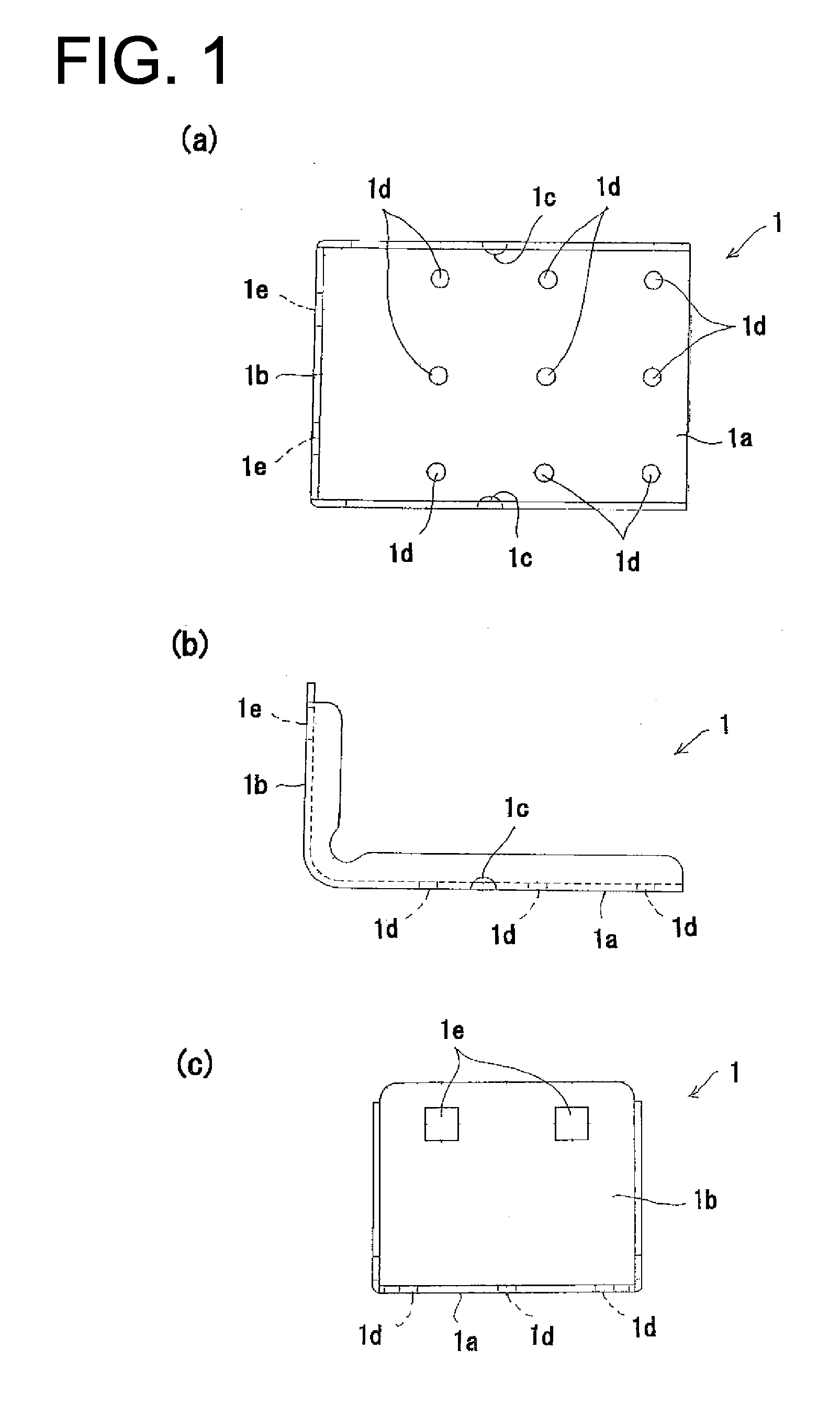
[0084]FIG. 1 shows a base metal fitting (1). (a) is a plan view, (b) is a front view, and (c) is a right side view.

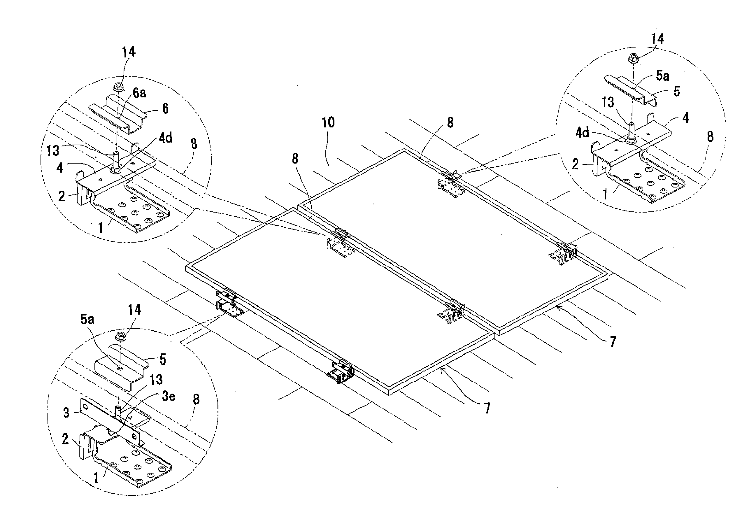
[0085]The base metal fitting (1) is fixed to a top surface of a slate roof, consists of a plate-like fixed part (1a) fixedly-contacting with the top surface of the roof and a plate-like extending part (1b) arranged perpendicular to the top surface of the roof, and as a whole is bent into L-shape in a front view.

[0086]The plate-like fixed part (1a) has several through holes (1c) (1d). Although the number of the through holes (1c) (1d) is not specifically limited, two through holes (1c) and nine through holes (1d) are formed in the illustrated drawings. Among these through holes (1c) (1d), the through holes (1c) formed at the both ends in the width direction of the plate-like fixed part (1a) are used as weep holes, and the remaining through holes (1d) are used as screw inser...

second embodiment

[0155]Next, the solar battery module fixture associated with the present invention will be set forth.

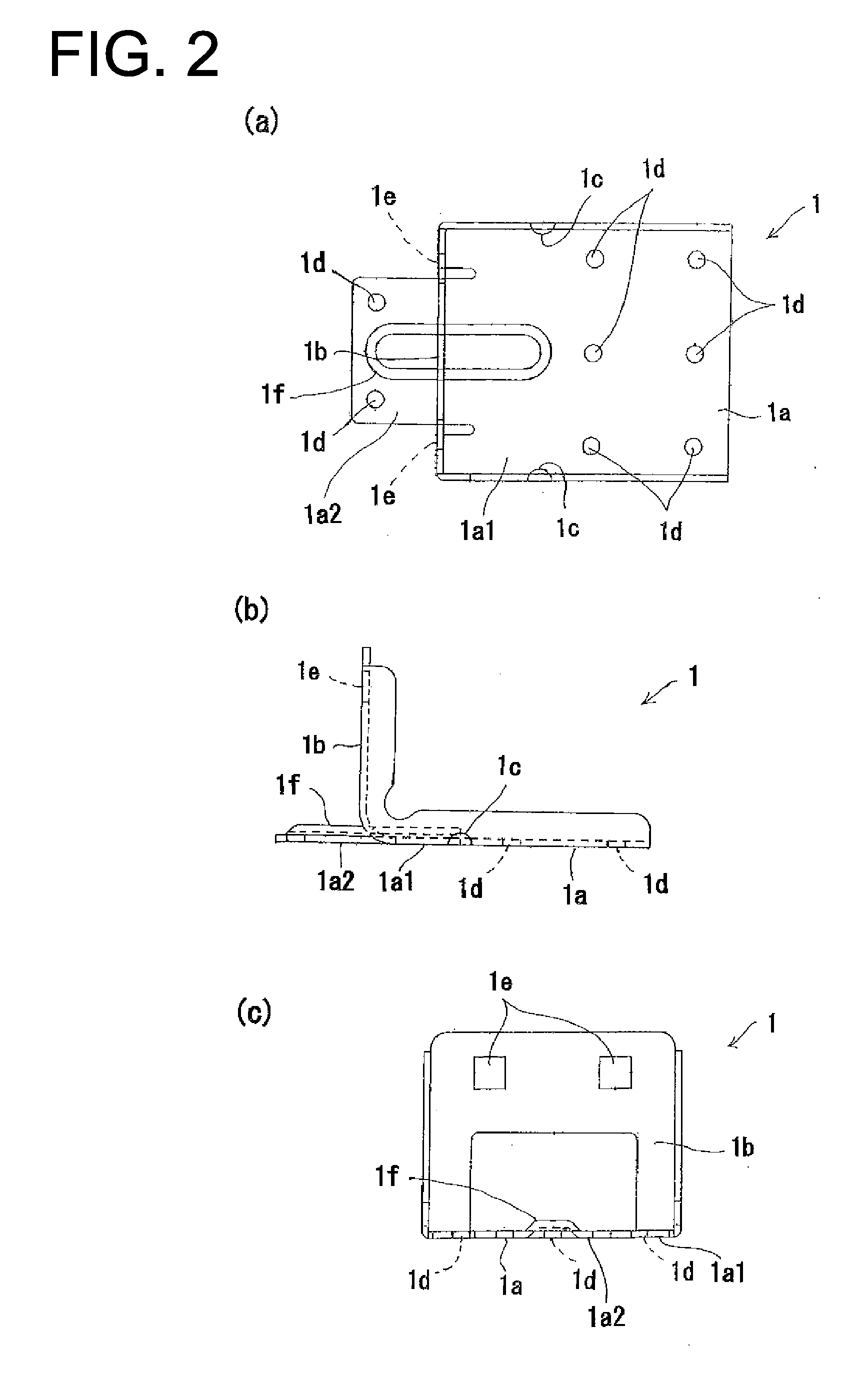
[0156]FIG. 16 illustrates a base metal fitting (21). (a) is a plan view, (b) is a front view, and (c) is a right side view.

[0157]The base metal fitting (21) is a metal fitting fixed on a top surface of the slate roof, consists of a plate-like fixed part fixedly coming into contact with the top surface of the roof and a plate-like extending part (21b) arranged longitudinally on the top surface of the roof, and is as a whole bent in a L-shape in a front view.

[0158]A plurality of the through holes (21c) and (21d) (two holes in an example of the drawing) are formed on the plate-like fixed part (21a). Although the number of through holes (21c) and (21d) is not specifically limited, in the example of FIG. 16, two through holes (21c) and two through holes (21d) are formed. Among these through holes (21c) and (21d), the through holes (21c) formed on both ends in a width direction of the plat...


PUM


Abstract

[Problem] To be able to reliably fix a solar battery module in an appropriate position on a roof, to have light weight and few components, and to be able to reliably prevent slipping and perform grounding during temporary placement when the fixing position of the solar battery module is adjusted. [Solution] The present invention comprises: a base metal fitting fixed to a rooftop surface; a height-adjusting metal fitting capable of sliding in a vertical direction relative to the base metal fitting; a position-adjusting metal fitting capable of sliding in a horizontal direction relative to the height-adjusting metal fitting; and a fixing metal fitting for sandwiching and fixing the solar battery module between the fixing metal fitting and the position-adjusting metal fitting from the top and bottom, the fixing metal fitting being attached relative to the position-adjusting metal fitting. The position-adjusting metal fitting has: a mounting board part for mounting the solar battery module; a stopper capable of making contact with the edge of a frame provided to the periphery of the solar battery module when the solar battery module is mounted on the mounting board part; and a protrusion for making contact with a conductor part of the frame when the solar battery module is fixed to ensure electrical conductance.

Description

TECHNICAL FIELD[0001]The present invention relates to a solar battery module fixture for fixing a solar battery module on a slate roof.BACKGROUND OF THE INVENTION[0002]Generally, attaching a solar battery module to a roof of a house etc. is performed by arranging a plurality of (for example, 4 to 8) fixtures along with outer frame of the solar battery module so that the fixture will be scattered throughout the module and by fixing the fixtures on the roof using a bolt etc.[0003]Specifically, the solar battery module (C) is fixed on a roof (A) by vertically holding a metal frame (E) surrounding an edge of a solar battery panel (D) between base metal fittings (B) and fixing metal fittings (G) which are fixed on the roof (A), as shown in FIG. 32 (a).[0004]However, there is a level difference (J) in a joint part of a roof tile (a slate tile), and thus it was required to provide a height adjusting butyl to eliminate the level difference (J) when the base metal fitting (B) was located on ...

Claims


Application Information

Patent Timeline
Patent Type & Authority Applications(United States)
IPC IPC(8): H01L31/042
CPCY02B10/12F24J2/5245F24J2/5258F24J2/5264H02S20/00H02S20/23Y02E10/47E04B2001/2439E04D1/34E04D3/36Y02B10/20F24S25/61F24S25/70F24S25/636Y02E10/50Y02B10/10
Inventor HAMAMURA, OSAMU
Owner NISSEI KINZOKU
Why Eureka
Try Eureka