DC commutator motor and automobile including the same

a commutator motor and commutator motor technology, applied in the direction of dynamo-electric machines, ac commutators, dynamo-electric components, etc., can solve the problems of increasing the tension between the winding conductor and the winding conductor, limiting the increase in the winding tension, and increasing the tension between the winding conductor and the terminal, so as to improve the commutating ability of the dc commutator motor and

Active Publication Date: 2013-10-10
HITACHI ASTEMO LTD
View PDF21 Cites 0 Cited by
  • Summary
  • Abstract
  • Description
  • Claims
  • Application Information

AI Technical Summary

Benefits of technology

[0013]This reduces the combined inductance of the upper coil and the lower coil. The reduction in combined inductance reduces the voltage (sparking voltage) applied to the commutator segments, improving the commutating ability of the DC commutator motor.
[0014]According to the present invention, a good commutating ability can be obtained and a reduction in an output power volume ratio can be suppressed.

Problems solved by technology

In the case with the DC commutator motor disclosed in JP-2007-151268-A, if its diameter is increased excessively to cope with the use of the high current, it takes an effort to route the winding conductor, posing a difficulty in winding the winding conductor.
There is also a limit to the increase in the tension set for the winding.
Furthermore, complexity of connecting the winding conductor and a terminal is increased, resulting in increased assembly man-hours, which is a factor to increase costs.
Crossover lines overlap with each other at ends of coils, and the ends of the coils become larger as the diameter of the winding conductor is increased, resulting in an increased size of the motor.
This, however, has posed a concern about a short circuit between the winding conductors, which are twisted.
This, however, has increased man-hours for the motor assembly, resulting in a cost increase.
Furthermore, ununiform resistance values of parallel armature coils cause a selective action, which leads to an excessive increase in temperature of the motor, resulting in a reduction in an output power volume ratio and efficiency of the motor.
In addition, the DC commutator motor, disclosed in JP-2007-151268-A, has presented a problem that the stabilization of commutation and the reduction of sparking voltage at the completion of the commutation may not be achieved.

Method used


Image

  • DC commutator motor and automobile including the same
  • DC commutator motor and automobile including the same
  • DC commutator motor and automobile including the same

Examples


modified embodiments

(Modified Embodiments)

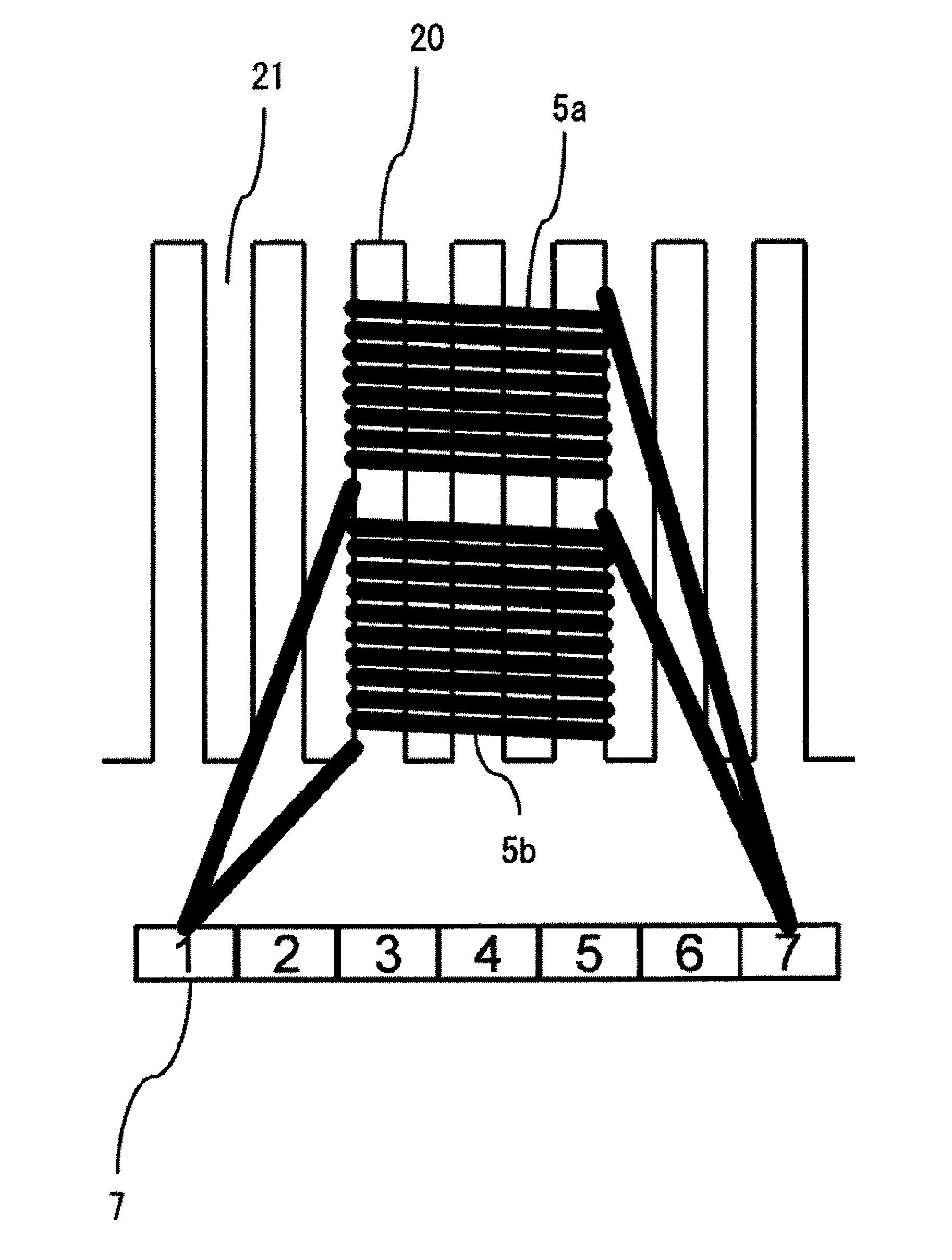
[0076]In the embodiment described above, one winding conductor is wound from the start point of the winding to the end point of the winding while the winding conductor is hooked to the hook portions 7b of the commutator segments 7, and thus, the commutator segment 7 connecting the end point of the winding of the lower coils 5b coincides with the commutator segment 7 connecting the start point of the winding of the upper coils 5a. This coincidence, however, does not have to take place.

[0077]In the present modified embodiment, the upper coils 5a are constituted by a first continuous winding conductor, while the lower coils 5b are constituted by a second continuous winding conductor. Here, the first winding conductor and the second winding conductor are separate winding conductors. Note that the first winding conductor and the second winding conductor have an identical wire diameter.

[0078]If one winding conductor is wound in a manner as if a line is continuously e...


PUM


Abstract

A DC commutator motor includes a yoke, a field magnet, and an armature. A shaft is positioned on a central axis of the armature. A plurality of commutator segments is positioned in a circumferential direction of the shaft. A plurality of armature slots is formed on an outer periphery of an armature core. An upper coil is wound the number of turns Na through two armature slots, which are located apart from each other with the predetermined number of armature slots therebetween, at their opening sides. A lower coil is connected in parallel with the upper coil and wound the number of turns Nb through the two armature slots at their bottom sides. The number of turns Na is smaller than the number of turns Nb.

Description

BACKGROUND OF THE INVENTION[0001]1. Field of the Invention[0002]The present invention relates to a DC commutator motor and an automobile including the same, and particularly, to a DC commutator motor including an upper coil and a lower coil connected in parallel as an armature winding, and an automobile including the same.[0003]2. Description of the Related Art[0004]DC commutator motors, with which high power can be obtained with ease, have been used as, for example, motors for driving hydraulic pumps for vehicles. In recent years, DC commutator motors have also started being used for auxiliary machines of an automobile besides hydraulic pumps in order to reduce fuel consumption of the automobile. The number of DC commutator motors mounted on an automobile is on the increase under such circumstances. To cope with this trend, a reduction in size and weight of a motor should be promoted while its output is maintained. Consequently, an output power volume ratio (a value obtained by div...

Claims


Application Information

Patent Timeline
Patent Type & Authority Applications(United States)
IPC IPC(8): H02K3/28
CPCH02K3/28H02K23/38H02K23/36
Inventor TANIGUCHI, TSUKASAIWAKI, HIDEFUMI
Owner HITACHI ASTEMO LTD
Why Eureka
Try Eureka