Master cylinder device and hydraulic brake system using the same

a technology of hydraulic brake and master cylinder, which is applied in the direction of braking system, rotary clutch, fluid coupling, etc., can solve the problems large resistance to the movement of the input piston by the operation force, and deteriorating operational feeling. , to achieve the effect of deteriorating operational feeling, friction force, and deteriorating operational feeling

Active Publication Date: 2013-10-17
TOYOTA JIDOSHA KK
View PDF1 Cites 13 Cited by
  • Summary
  • Abstract
  • Description
  • Claims
  • Application Information

AI Technical Summary

Benefits of technology

[0004]In the master cylinder device disclosed in the above patent literature, when the pressure receiving piston and the input piston move relative to each other in the master cylinder device, a seal between the pistons generates a friction force. Therefore, when the pressure receiving piston is moved by the brake fluid of a high pressure, a force causing a movement of the input piston acts on the input piston due to the friction force, whereby operational feeling in a brake operation is deteriorated. In addition, the above seal defines the inter-piston chamber and the input chamber. The pressure of the brake fluid in the input chamber becomes considerably high when a hydraulic brake force generated in the brake device is comparatively large. Therefore, a high-pressure seal is employed as the above seal. Commonly, the high-pressure seal generates the friction force to be comparatively large. Consequently, a problem of the above deterioration of operational feeling appears more significantly. In addition, as the friction force becomes large, a resistance upon a movement of the input piston by the operation force becomes large. This also deteriorates operational feeling in a brake operation. In the master cylinder device, there are left many rooms for improvements including an improvement for coping with the deterioration of operational feeling. So, if any improvement is carried out, it is possible to improve utility of the master cylinder device. The present invention is developed in the light of the current situation described above. It is therefore an object of the present invention to improve utility of a master cylinder device and a hydraulic brake system using the device.

Problems solved by technology

Therefore, when the pressure receiving piston is moved by the brake fluid of a high pressure, a force causing a movement of the input piston acts on the input piston due to the friction force, whereby operational feeling in a brake operation is deteriorated.
Consequently, a problem of the above deterioration of operational feeling appears more significantly.
In addition, as the friction force becomes large, a resistance upon a movement of the input piston by the operation force becomes large.
This also deteriorates operational feeling in a brake operation.

Method used


Image

  • Master cylinder device and hydraulic brake system using the same
  • Master cylinder device and hydraulic brake system using the same
  • Master cylinder device and hydraulic brake system using the same

Examples


first embodiment

>

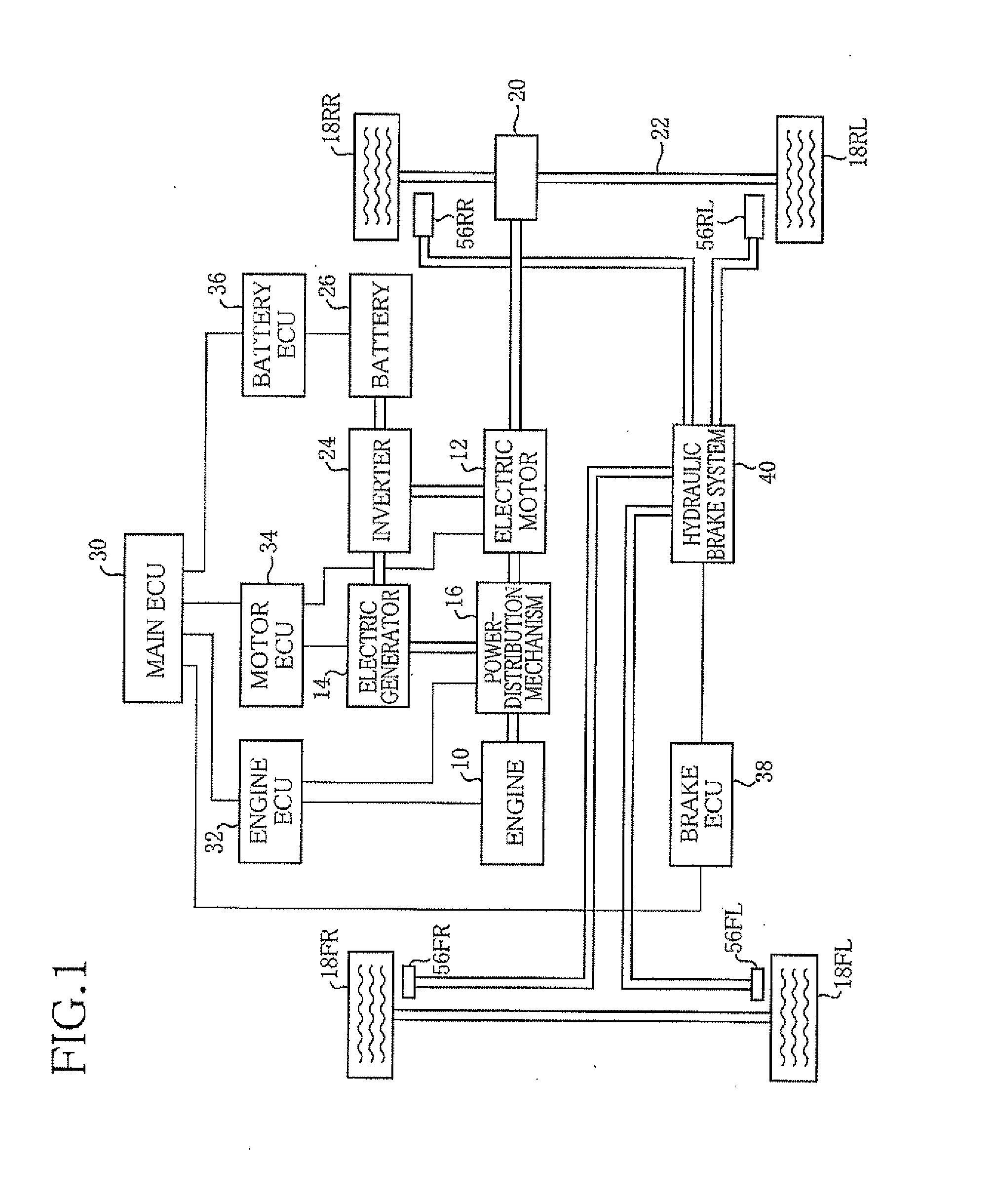
[0239]FIG. 1 schematically illustrates a drive system and a brake system of a hybrid vehicle equipped with a master cylinder device of a first embodiment. The vehicle is equipped with an engine 10 and an electric motor 12 as power sources, and also an electric generator 14 for generating electricity by an output power of the engine 10. The engine 10, the electric motor 12, and the electric generator 14 are connected to one another via a power-distribution mechanism 16. By controlling the power-distribution mechanism 16, the power of the engine 10 can be divided into a power for driving the electric generator 14 and a power for rotating drive wheels among four wheels 18, and a power of the electric motor 12 can be transmitted to the drive wheels. In other words, the power-distribution mechanism 16 functions as a speed-change mechanism with respect to a driving power which is transmitted to the drive wheels via a speed reducer 20 and a drive shaft 22. It is noted that, while some of ...

second embodiment

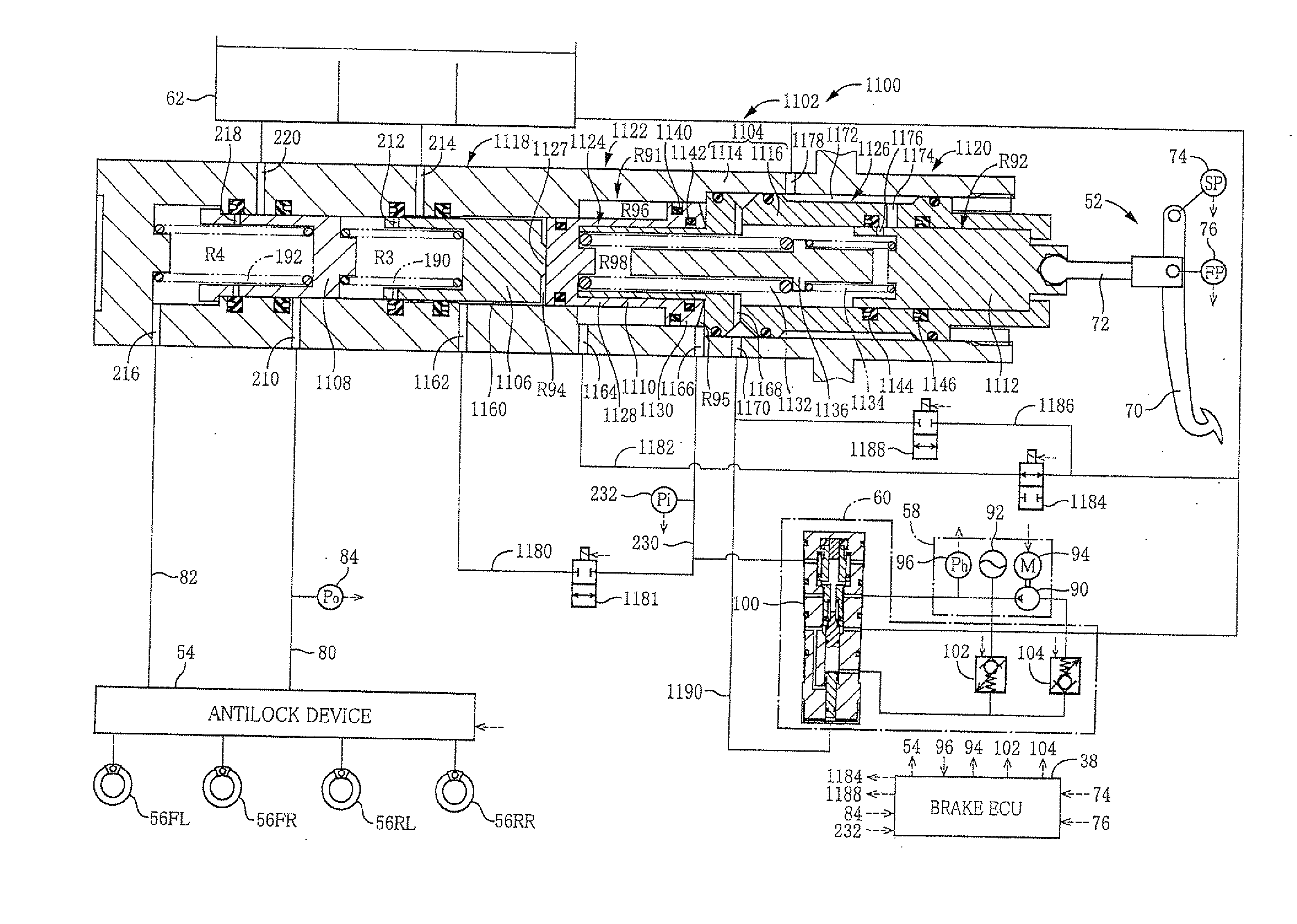
[0284]FIG. 5 schematically represents a hydraulic brake system 300 of the second embodiment. The hydraulic brake system 300 has a master cylinder device 302. The hydraulic brake system 300 generally has the same structure as the hydraulic brake system 40 of the first embodiment. In the following description, with consideration for abbreviating the explanation, different construction and actuation from the hydraulic brake system 40 of the first embodiment will be described but the same construction and actuation as the hydraulic brake system 40 of the first embodiment are omitted.

>

[0285]The master cylinder device 302 is categorized into the Input Piston Free Type Master Cylinder Device, and has a housing 304 being a casing, a first pressurizing piston 306 and a second pressurizing piston 308 which pressurize the brake fluid to be supplied to the brake devices 56, and an input piston 310 to which an operation of the driver is inputted via the operation device 52.

[0286]The housing 304 ...

third embodiment

[0303]FIG. 6 schematically represents a hydraulic brake system 400 of the third embodiment. The hydraulic brake system 400 has a master cylinder device 402. The hydraulic brake system 400 generally has the same structure as each of the hydraulic brake systems of the first and the second embodiments. In the following description, with consideration for abbreviating the explanation, different construction and actuation from the hydraulic brake systems will be described but the same construction and actuation as the hydraulic brake systems are omitted.

>

[0304]The master cylinder device 402 is categorized into the Input Piston Free Type Master Cylinder, and has a housing 404 being a casing, a first pressurizing piston 406 and a second pressurizing piston 408 which pressurize the brake fluid to be supplied to the brake devices 56, and an input piston 410 to which an operation of the driver is inputted via the operation device 52.

[0305]The housing 404 mainly includes three members, specifi...


PUM


Abstract

A master cylinder device includes a housing whose front side end is closed and which includes a third housing member separating an interior of the housing into a front side chamber and a rear side chamber and having an opening through the third housing member, a first pressurizing piston which includes a main body portion disposed in the front side chamber and which is moved forward by receiving a force for pressurizing the brake fluid to be supplied to a brake devices, and an input piston. In the master cylinder device, an input chamber into which a brake fluid is introduced is defined between a rear end of the main body portion of the first pressurizing piston and the third housing member. The input piston is fitted in the housing with seals, whereby, an inter-piston chamber across which the input piston and the pressure receiving piston face to each other.

Description

TECHNICAL FIELD[0001]This invention relates to a master cylinder device for pressurizing a brake fluid and supplying the pressurized brake fluid to a brake device provided in a wheel, and a hydraulic brake system using the master cylinder device.BACKGROUND ART[0002]Some master cylinder devices, such as a master cylinder device disclosed in the following patent literature, can pressurize a brake fluid depending on a pressure of a brake fluid introduced from a high pressure source irrespective of an operation force for operating a brake operation member by a driver. This master cylinder device includes a pressure receiving piston which moves forward by a pressure of a brake fluid in an input chamber, that is, a fluid chamber into which the brake fluid is introduced and which then pressurizes a brake fluid, and an input piston which is fitted in the pressure receiving piston at a blind hole thereof being open rearward and which moves forward by a brake operation. Between a bottom porti...

Claims


Application Information

Patent Timeline
Patent Type & Authority Applications(United States)
IPC IPC(8): F15B15/00
CPCF15B15/00B60T1/10B60T7/042B60T8/3265B60T8/4077B60T11/224B60T13/145B60T13/146B60T13/662B60T8/17B60T11/20B60T17/18B60T11/165
Inventor ISONO, HIROSHI
Owner TOYOTA JIDOSHA KK
Why Eureka
Try Eureka