Underwater moving apparatus and moving method thereof

a moving apparatus and underwater technology, applied in underwater equipment, special-purpose vessels, vessel construction, etc., can solve the problems of underwater moving apparatus, difficult to control a posture, underwater moving apparatus, etc., and achieve the effect of safe operation, easy movement to the target location, and reduced resistance to fluid

Active Publication Date: 2013-10-17
SAMSUNG HEAVY IND CO LTD
View PDF12 Cites 39 Cited by
  • Summary
  • Abstract
  • Description
  • Claims
  • Application Information

AI Technical Summary

Benefits of technology

[0041]The underwater moving apparatus according to the exemplary embodiment of the present invention converts a posture into a vertical posture by adjusting buoyancy and moving a center of gravity, and moves down quickly to a desired water depth by generating thrust so as to easily move to the target location. Further, the underwater moving apparatus stops at a predetermined water depth or a predetermined distance from the sea floor, converts a posture into a horizontal posture, and then moves to the target location, and therefore the underwater moving apparatus may be safely operated.
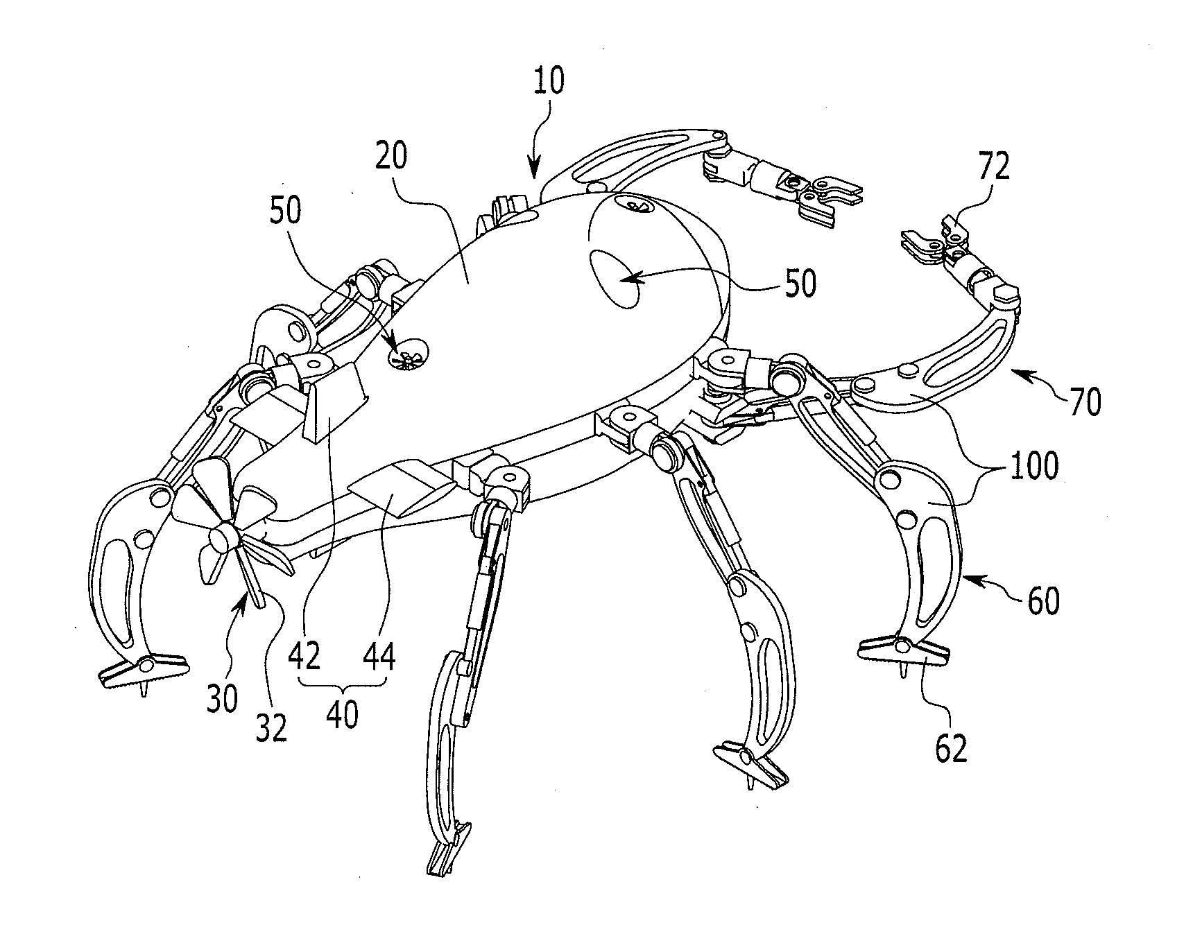
[0042]In addition, the underwater moving apparatus has a streamlined body and multi-joint legs, which are folded when the underwater moving apparatus swims, so that resistance of fluid may be reduced, and the underwater moving apparatus may adapt to a high flow velocity, which is generated due to influence by the tide and the ocean current.

Problems solved by technology

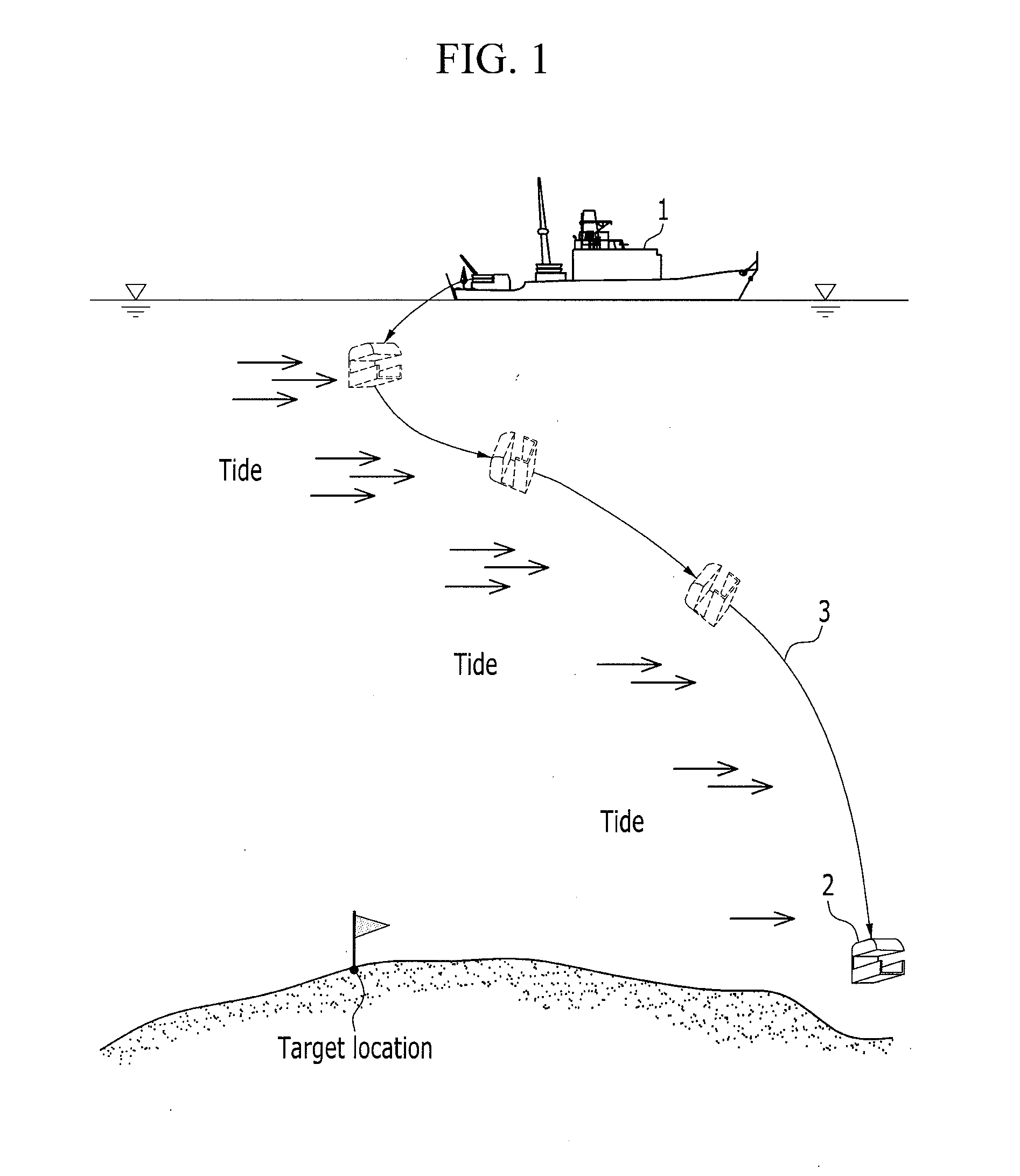
However, it is difficult to control a posture and a movement of the underwater moving apparatus 2 of the related art in an area of which a flow velocity is high because of influence by the tide, such as the west coast of Korea, and thereby it is not easy to allow the underwater moving apparatus 2 to approach a desired location.
That is, as illustrated in FIG. 1, there is a problem in that the underwater moving apparatus 2 does not make a posture but is carried away due to a high flow velocity, and consumes a large amount of energy because it is difficult to control a posture and a movement.
Therefore, it is difficult to control a movement and a posture when the velocity of the ocean current is high.
In addition, because the underwater moving apparatus is moved only by the thrusters and a propelling device, there is a problem in that it is difficult to move the underwater moving apparatus in a state of being seated on a floor surface of the deep sea floor.

Method used


Image

  • Underwater moving apparatus and moving method thereof
  • Underwater moving apparatus and moving method thereof
  • Underwater moving apparatus and moving method thereof

Examples


Embodiment Construction

[0061]In the following detailed description, only certain exemplary embodiments of the present invention have been shown and described, simply by way of illustration. As those skilled in the art would realize, the described embodiments may be modified in various different ways, all without departing from the spirit or scope of the present invention. Accordingly, the drawings and description are to be regarded as illustrative in nature and not restrictive. Like reference numerals designate like elements throughout the specification.

[0062]In the specification, unless explicitly described to the contrary, the word “comprise” and variations such as “comprises” or “comprising”, will be understood to imply the inclusion of stated elements but not the exclusion of any other elements. In addition, the terminologies such as “ . . . part”, “ . . . device”, “ . . . module”, or “ . . . member”, which are disclosed in the specification, refer to a unit of a constituent element which performs at ...


PUM


Abstract

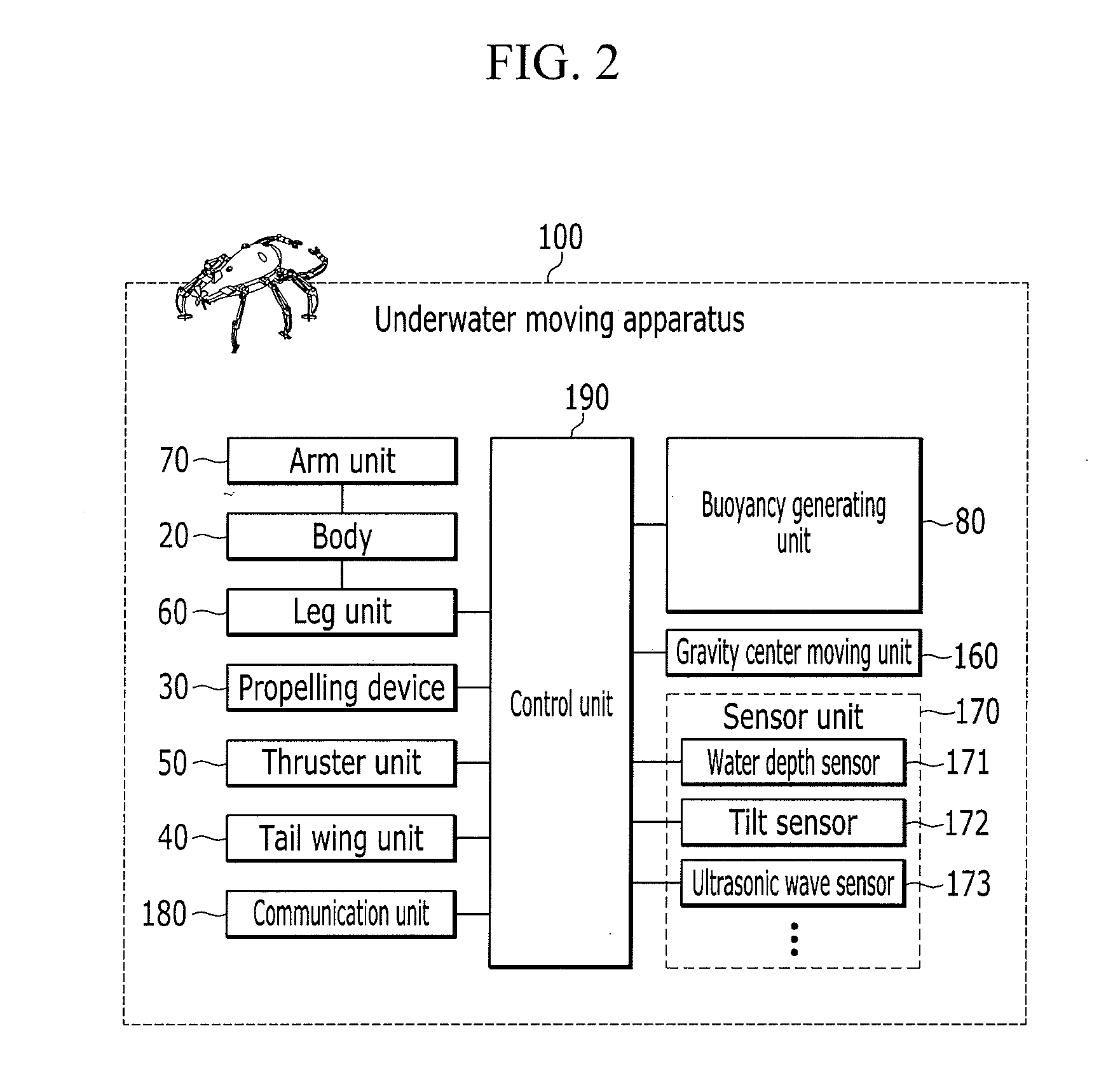
Disclosed are an underwater moving apparatus and a moving method thereof. The underwater moving apparatus of an exemplary embodiment of the present invention includes a body; a propelling device installed on a rear side of the body; a thruster unit including an up and down directional thruster and a left and right directional thruster installed at the body; and a plurality of leg units positioned at both side portions of the body and including a multi-joint module.

Description

TECHNICAL FIELD[0001]The present invention relates to an underwater moving apparatus and a moving method thereof.BACKGROUND ART[0002]In general, an underwater moving apparatus is used for exploration of resources on a sea floor, salvage of sunken vessels, removing of oil, installation of submarine cables, repairing of underwater structure, or the like, and is being developed in various types in accordance with the use and an operational method.[0003]The underwater moving apparatus may be classified, in accordance with a control method, into a remotely-operated vehicle (ROV) in which a cable is connected to the underwater moving apparatus, and an autonomous underwater vehicles (AUV) which is operated by its own power without using a cable, and is equipped with a system which determines a direction and a distance to be investigated in accordance with topography of the sea floor, and transmits the investigated data from the sea floor to a mother ship.[0004]Meanwhile, FIG. 1 is a concep...

Claims


Application Information

Patent Timeline
Patent Type & Authority Applications(United States)
IPC IPC(8): B63G8/08B63G8/16B63G8/22
CPCB63G8/08B63G8/22B63G8/16B62D57/032B63B1/04B63G8/001B63G8/14B63G8/26B63G2008/004B63G2008/007B25J5/00B25J13/08B63C11/48
Inventor KIM, JAEHOONPARK, YOUNGJUNEUN, JONGHOCHOI, JONGUNGLEE, JAEYONGJOO, SUNGMOONJEONG, HIEYONGLEE, DONGHUN
Owner SAMSUNG HEAVY IND CO LTD
Why Eureka
Try Eureka