Method and an Apparatus for Producing a Solar Cell Module and a Solar Cell Module

a technology of solar cell module and apparatus, which is applied in the direction of turning machine accessories, final product manufacturing, drawing profiling tools, etc., can solve the problems of one costly component difficult for solar energy generation technique to successfully compete with other more mature energy generation techniques, and production cost of solar cell module, so as to facilitate the separation of solar cell film from the surrogate substrate. , the effect of positive influen

Inactive Publication Date: 2013-10-17
SOLARWAVE
View PDF2 Cites 8 Cited by
  • Summary
  • Abstract
  • Description
  • Claims
  • Application Information

AI Technical Summary

Benefits of technology

[0013]The combination of these steps makes it possible to reliably produce a very thin film of at least one, in the reality mostly a great number, solar cell module, which may together with the protective plastic layer carriers on both sides of the solar cell film well have a thickness in the order of some millimetres or even less. By depositing a material forming a release layer onto said surrogate substrate the separation of the solar cell film from the surrogate substrate will be facilitated. This separation may be carried out without damaging the solar cell film thanks to the application of said first protective layer onto the solar cell film before or in connection with the separation. It is pointed out that “release layer” is here to be interpreted as a layer applied purely for facilitating separation of the solar cell film from the surrogate substrate and not forming any part involved in the operation of the final solar cell film product.
[0014]According to an embodiment of the invention said release layer is in step a) deposited onto a belt, such as a steel belt, having an average surface roughness ≦0.2 μm, ≦0.1 μm or ≦0.05 μm. The use of such a smooth belt as surrogate substrate means that the release layer material may be deposited onto the belt while making a weak contact thereto facilitating said separation. The use of a steel belt as surrogate substrate enables the use of high temperatures during said depositing of layers, which has a positive influence upon the final result of the method.
[0015]According to another embodiment of the invention said belt is cleaned after having passed the separating step d) before returning to a place along said loop for carrying out step a) for acting as a surrogate substrate again. Such cleaning is advantageous even if the release layer would in the separating step be totally removed from the belt.
[0019]According to another embodiment of the invention a layer for a back contact or a layer for a front contact of the solar cell film is in step b) deposited onto said release layer, and in the latter case the release layer is removed from said front contact in step d) when the material of the release layer is not transparent to light. Thus, it is possible both to have the back contact and the front contact deposited closest to the belt during the production of the solar cell module, but in the latter case the release layer has to be removed when it is of a material not transparent to light. However, when the release layer material is transparent to light and left onto the front contact it may even increase the efficiency of the solar cell module by providing this with anti-reflecting properties.
[0026]The invention also relates to a solar cell module produced by carrying out a method according to the present invention. The advantages, especially with respect to low costs, of such a solar cell module appear clearly from the above discussion of the method according to the present invention.

Problems solved by technology

A problem in common to known methods for producing solar cell modules is that they are either costly to carry out or otherwise result in a production cost of the solar cell module making it difficult for the solar energy generation technique to successfully compete with other more mature energy generation techniques.
One costly component of solar cell modules may be a rather thick carrier of the solar cell film including active layer and front and back contacts.

Method used


Image

  • Method and an Apparatus for Producing a Solar Cell Module and a Solar Cell Module
  • Method and an Apparatus for Producing a Solar Cell Module and a Solar Cell Module
  • Method and an Apparatus for Producing a Solar Cell Module and a Solar Cell Module

Examples


Embodiment Construction

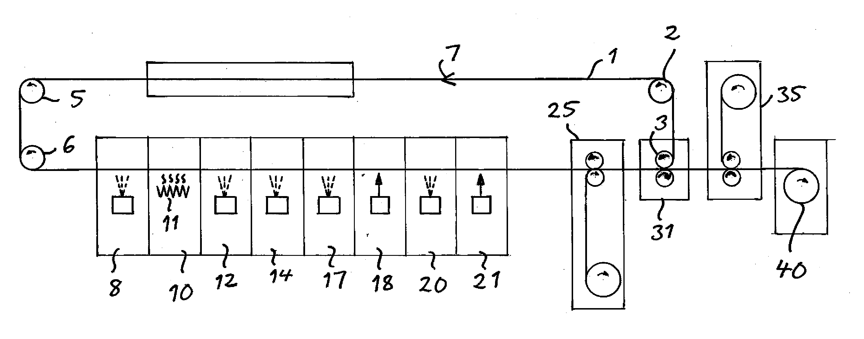
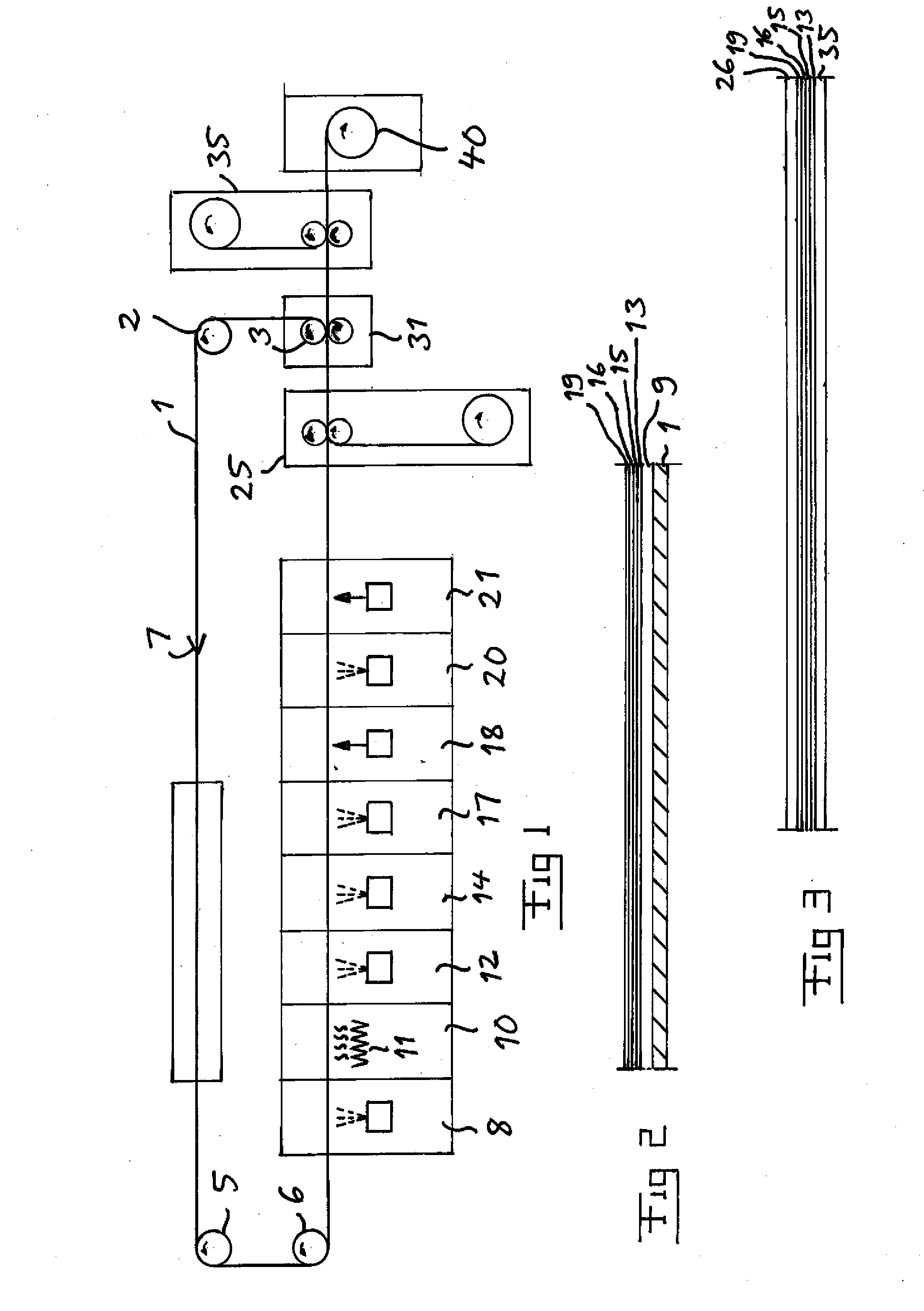
[0041]Methods for producing a continuous film of at least one solar cell module according to different embodiments of the invention will now be described while referring to FIG. 1 showing the general construction of an apparatus for continuously producing a continuous film of at least one solar cell module according to an embodiment of the invention while in parallel making reference to FIG. 2-8 for explaining different steps of such a method.

[0042]The apparatus comprises an endless belt 1 preferably of steel with a low average surface roughness and means in the form of diverting rollers 3-6 configured to move the belt 1 in a continuous loop in the direction of the arrow 7. The belt may have a width of as much as 500 cm and a length of more than 100 meters.

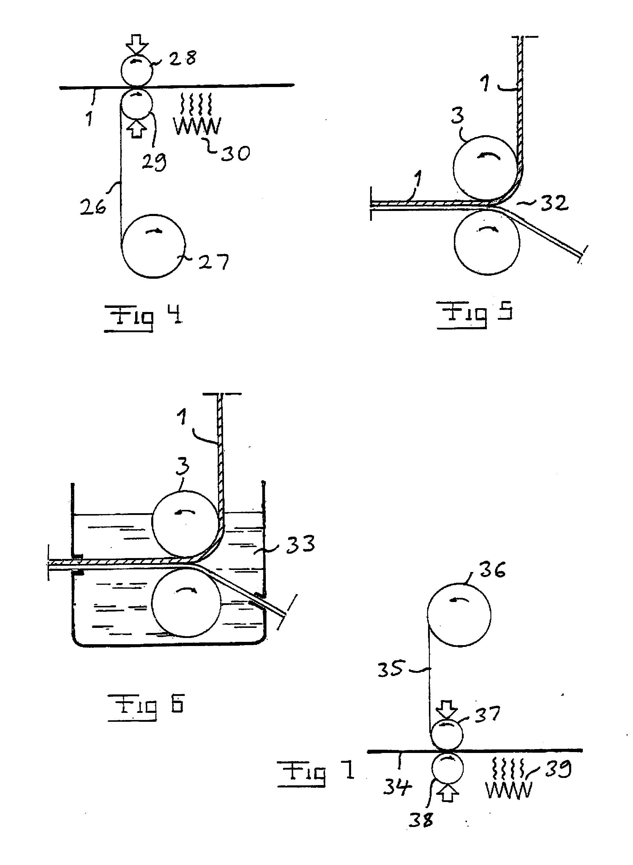
[0043]The belt is configured to form a surrogate substrate and will in the path along said loop first reach a chamber 8 in which a release layer 9 (see FIG. 2) is deposited onto the belt 1. The release layer may be deposited by fo...


PUM

PropertyMeasurementUnit
surface roughnessaaaaaaaaaa

Abstract

A method for producing a continuous film of at least one solar cell module comprises the steps of depositing (8) a material forming a release layer onto a surrogate substrate in the form of a belt (1) being moved in a continuous loop, depositing (12, 14, 17) layers forming a solar cell film onto said release layer, applying (25) a first protective plastic layer onto the solar cell film, separating (31) a film including at least said solar cell film and said plastic layer attached thereto from said belt, and applying (35) a second protective plastic layer on the side of said film separated opposite to said first protective plastic layer.

Description

TECHNICAL FIELD OF THE INVENTION AND BACKGROUND ART[0001]The present invention relates to a method for producing a continuous film of at least one solar cell module, a solar cell module produced by carrying out such a method as well as an apparatus for continuously producing a continuous film of at least one solar cell module.[0002]A problem in common to known methods for producing solar cell modules is that they are either costly to carry out or otherwise result in a production cost of the solar cell module making it difficult for the solar energy generation technique to successfully compete with other more mature energy generation techniques.[0003]One costly component of solar cell modules may be a rather thick carrier of the solar cell film including active layer and front and back contacts. This thick carrier is mostly made of glass.[0004]A method for producing a continuous film of solar cell modules enabling production of solar cell modules with a much thinner carrier is known ...

Claims


Application Information

Patent Timeline
Patent Type & Authority Applications(United States)
IPC IPC(8): H01L31/0216H01L31/18
CPCH01L31/02167H01L31/18H01L21/67173H01L21/6776H01L31/048H01L31/1896H01L31/03926H01L31/03928H01L31/206C23C14/0005C23C14/0629C23C14/562C23C16/01C23C16/305C23C16/545C23C18/1212C23C18/1295H01L31/1892Y02E10/541Y02P70/50
Inventor SKORELID, BENGTLARSSON, THOMAS
Owner SOLARWAVE
Why Eureka
Try Eureka