Axial load sharing bearing system and associated method of use

a technology of axial load sharing bearings and bearings, which is applied in the direction of elastic bearings, mechanical energy handling, mechanical equipment, etc., can solve the problems of high cost, high cost of sleeve and opposite end shaft plate, single bearing load,

Active Publication Date: 2013-10-17
REGAL BELOIT AMERICA +1
View PDF14 Cites 18 Cited by
  • Summary
  • Abstract
  • Description
  • Claims
  • Application Information

AI Technical Summary

Problems solved by technology

A major problem with this motor is that the load is placed on a single bearing on the shaft end of the motor.
There is also a complex and costly sleeve and opposite end shaft plate.
Moreover, the shaft for the rotor is a costly and complex structure to manufacture.

Method used


Image

  • Axial load sharing bearing system and associated method of use
  • Axial load sharing bearing system and associated method of use
  • Axial load sharing bearing system and associated method of use

Examples


Embodiment Construction

[0026]In the following detailed description, numerous specific details are set forth in order to provide a thorough understanding of the invention. However, it will be understood by those skilled in the art that the present invention may be practiced without these specific details. In other instances, well-known methods, procedures, and components have not been described in detail so as to obscure the present invention.

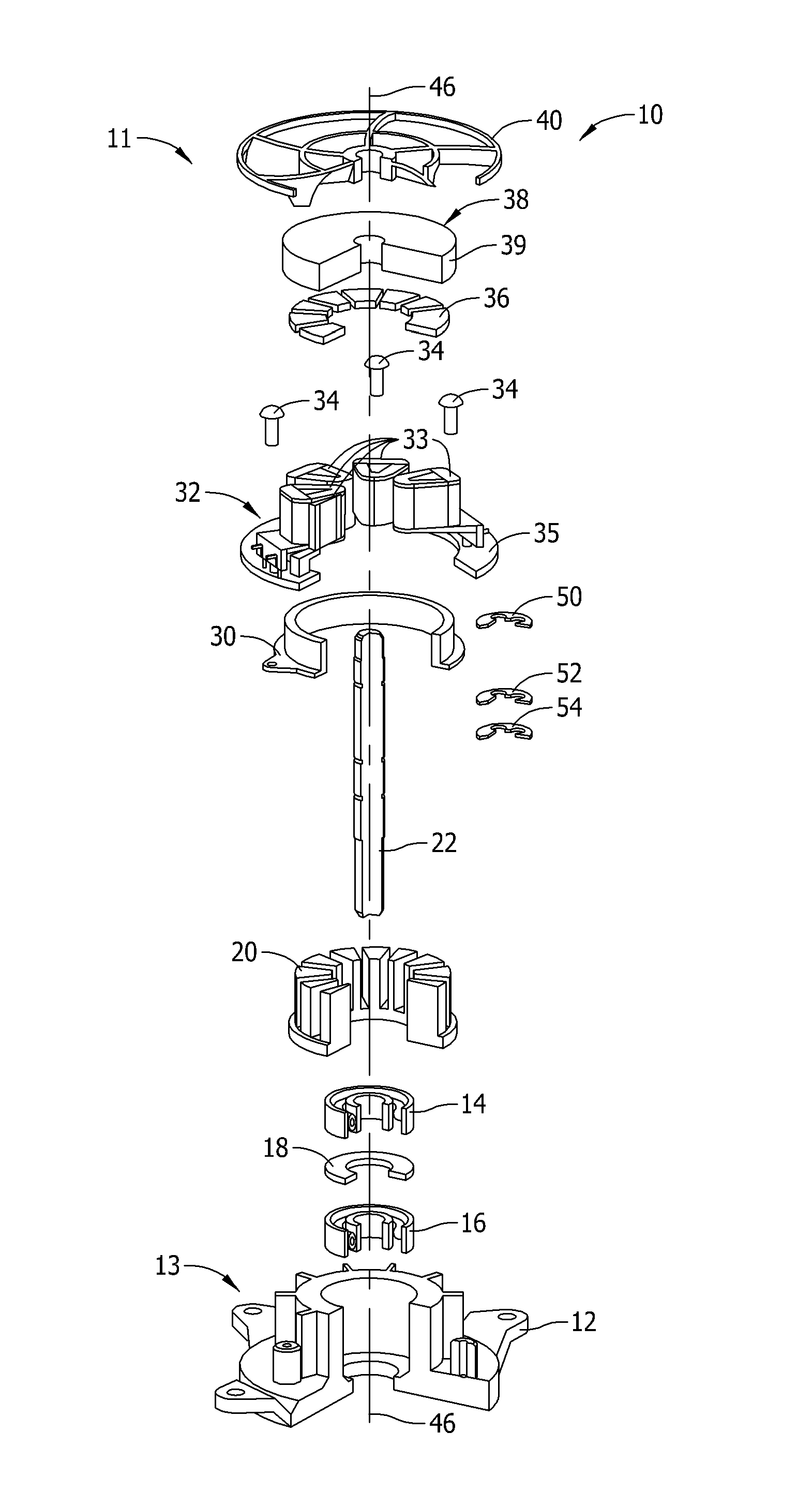
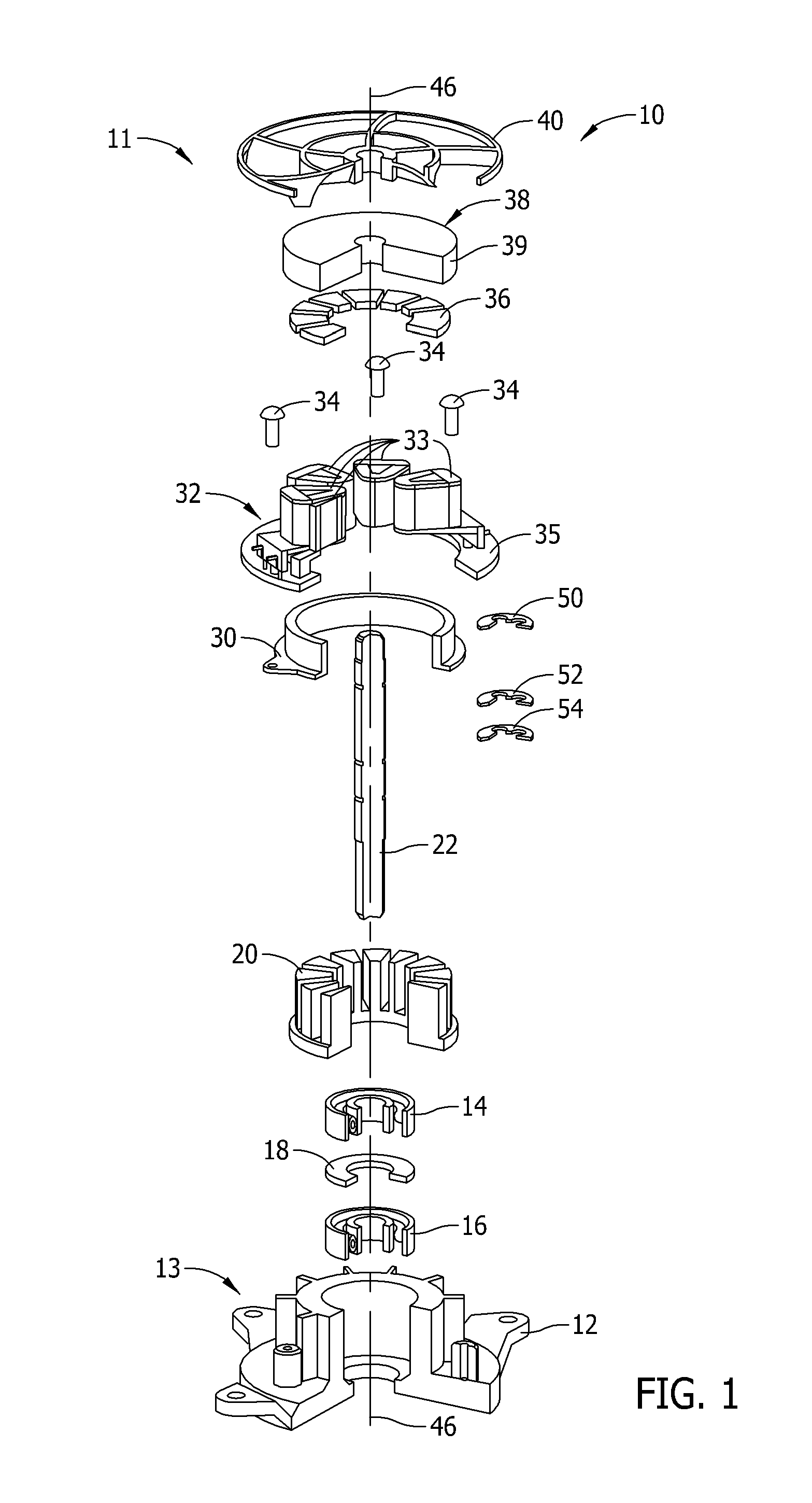
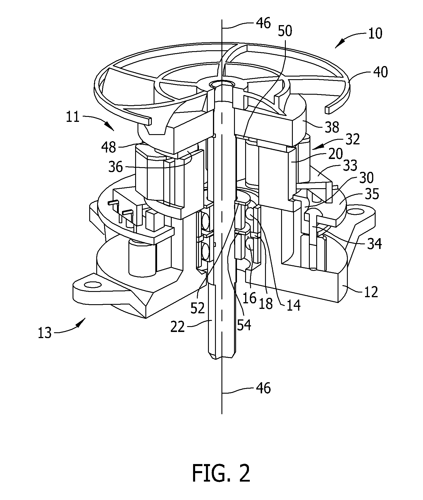
[0027]Referring now to FIGS. 1 and 2, an axial flux load sharing machine of the present invention is generally indicated by numeral 10. FIG. 1 is an exploded, partially cut-away view of the axial flux load sharing machine 10 and FIG. 2 is a partially cut-away view of the axial flux load sharing machine 10. Components common to FIGS. 1 and 2 are identified with the same reference numerals. Components are described herein as including a top surface 11 generally facing what is referred to herein as a top of the axial flux load sharing electric machine 10, and a bottom su...


PUM


Abstract

An axial flux electric machine and associated method of use that includes a shaft, a rotor attached to the shaft, a plurality of permanent magnets positioned underneath the rotor, an electrical winding positioned below the plurality of permanent magnets, a stator that encircles the shaft that is located below the rotor, a first bearing assembly located below the stator and encircling the shaft of the rotor, a second bearing assembly located below the first bearing assembly and encircling the shaft, and a spring mechanism, located between the first bearing assembly and the second bearing assembly, to distribute load placed on the shaft between the first bearing assembly and the second bearing assembly.

Description

BACKGROUND OF THE INVENTION[0001]A significant application for an electric motor is to operate a pump or a blower. This type of electric motor typically utilizes a permanent magnet electrical motor and would preferably utilize a planar array of magnets. A typical permanent magnet electrical motor can include an alternating current induction motor. One type of alternating induction motor is a radial flux motor, where the flux extends radially outward from the axis of rotation. Another type of electric motor is an electronically commutated motor. An electronically commutated motor may include a permanent magnet alternating current motor, a variable reluctance motor, and a brushless direct current motor. An electronically commutated motor typically operates at a higher efficiency than an alternating current induction motor. There is an axial flux configuration for an electronically commutated motor in which the flux in the air gap extends in a direction that is parallel to the axis of ...

Claims


Application Information

Patent Timeline
Patent Type & Authority Applications(United States)
IPC IPC(8): H02K5/173H02K5/16
CPCH02K21/24H02K5/1735F16C41/02F16C19/54F16C2380/26H02K5/1732H02K7/14H02K1/2795F16C27/00F16C27/04H02K5/16H02K5/173H02K7/08
Inventor ZIEGLER, WILLIAM A.SMITH, MICHAEL D.LANGFORD, CHARLES RICHARD
Owner REGAL BELOIT AMERICA
Why Eureka
Try Eureka