Compressed gas supply unit, compressed gas supply apparatus and control method of said unit and said apparatus

a technology of compressed gas and compressor, which is applied in the direction of mechanical equipment, machines/engines, liquid fuel engines, etc., can solve the problems of system security problems, system requirements for network line construction costs, and inability to accurately calculate the surplus of compressors, etc., to accurately grasp the abnormality of compressors, accurately determine the presence or absence of compressor abnormalities, and accurately determine the effect of compressor abnormalities

Inactive Publication Date: 2013-10-17
ANEST IWATA CORP
View PDF7 Cites 16 Cited by
  • Summary
  • Abstract
  • Description
  • Claims
  • Application Information

AI Technical Summary

Benefits of technology

[0010]In view of the problem of the conventional art described above, a first object of the present invention is to provide a compressed gas supply unit including a plurality of compressors which allows an equal load operation of the plurality of compressors while monitoring the operating state of each compressor and achieves energy saving and saving of a maintenance cost by using the equal load operation and control of the number of compressors under operating condition in combination. A second object of the present invention is to realize a low-cost remote control unit without any security problem in a case where a plurality of the compressed gas supply units disposed at positions apart from each other are remotely controlled.

Problems solved by technology

Although Japanese Patent Application Laid-open No. 2010-53733 discloses that the surplus of the ability of each compressor is calculated from the power consumption of each compressor, the pressure on the discharge side of the compressor also influences the power consumption of the compressor, and hence it is not possible to accurately calculate the surplus of the compressor only from the power consumption of the compressor.
In the system in which the compressor provided in the client plant and the personal computer provided in the monitoring center or the like are connected with the LAN cable as the remote monitoring system of a compressed gas supply apparatus, information on other clients may be leaked out of the LAN cable, and hence the system has a security problem.
In addition, the system requires a construction cost for providing a network line to the compressor.

Method used


Image

  • Compressed gas supply unit, compressed gas supply apparatus and control method of said unit and said apparatus
  • Compressed gas supply unit, compressed gas supply apparatus and control method of said unit and said apparatus
  • Compressed gas supply unit, compressed gas supply apparatus and control method of said unit and said apparatus

Examples


first embodiment

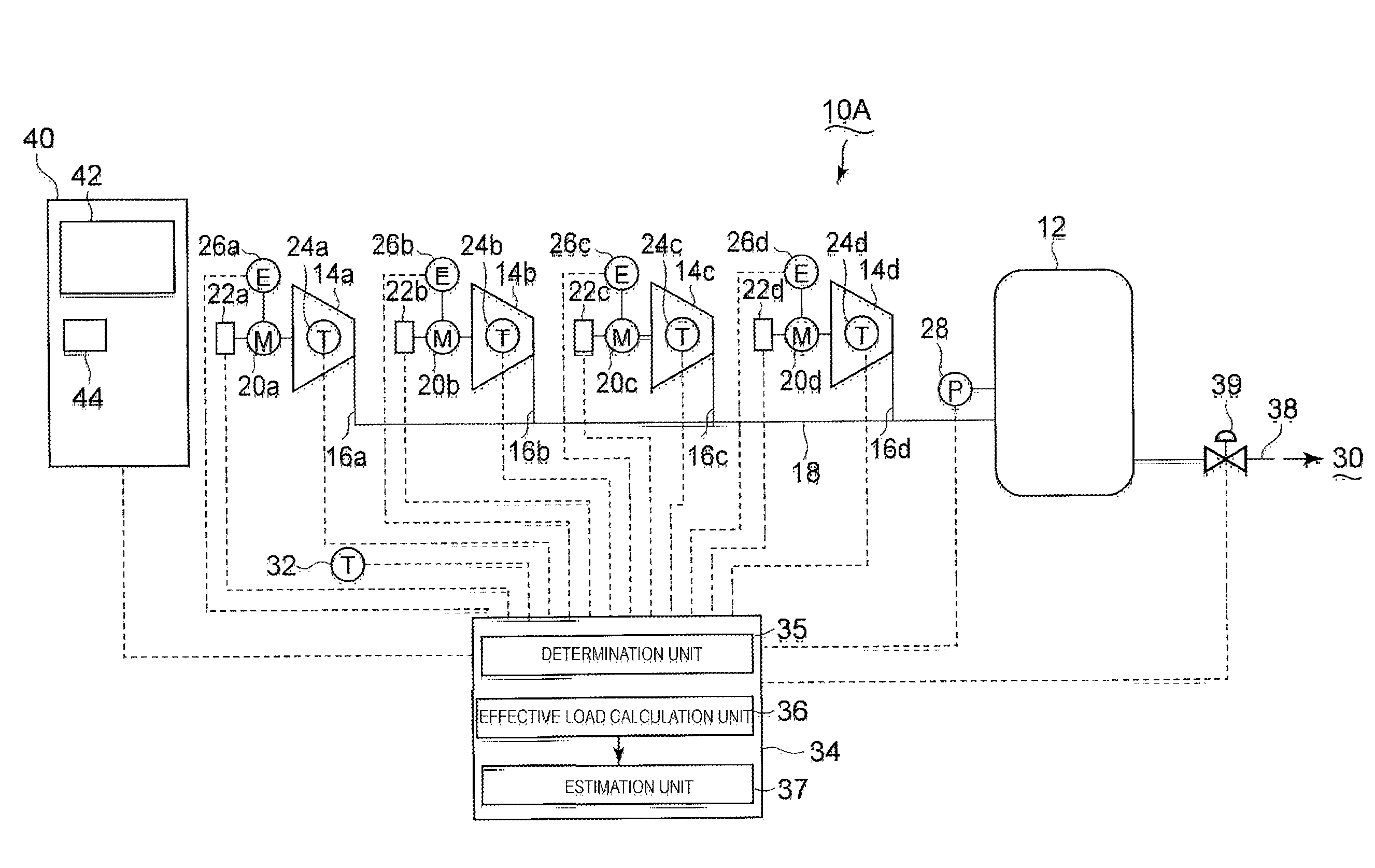
[0040]A first embodiment of each of an apparatus of a first aspect of the present invention and a method of a first aspect of the present invention will be described with reference to FIGS. 1 and 2. A compressed gas supply unit 10A of the present embodiment includes one storage tank 12 and four compressors 14a to 14d. Discharge paths 16a to 16d of the individual compressors are connected to a main supply pipe 18, and the main supply pipe 18 is connected to the storage tank 12. Gas discharged from each compressor flows through the main supply pipe 18 and is stored in the storage tank 12.

[0041]The individual compressors are provided with drive motors 20a to 20d and inverters 22a to 22d which can control the RPMs of the drive motors steplessly. With this, the RPMs of the individual motors can be individually controlled. Temperature sensors 24a to 24d which detect the temperatures of compressed gas are provided on the partitions of compression chambers of the individual compressors. The...

second embodiment

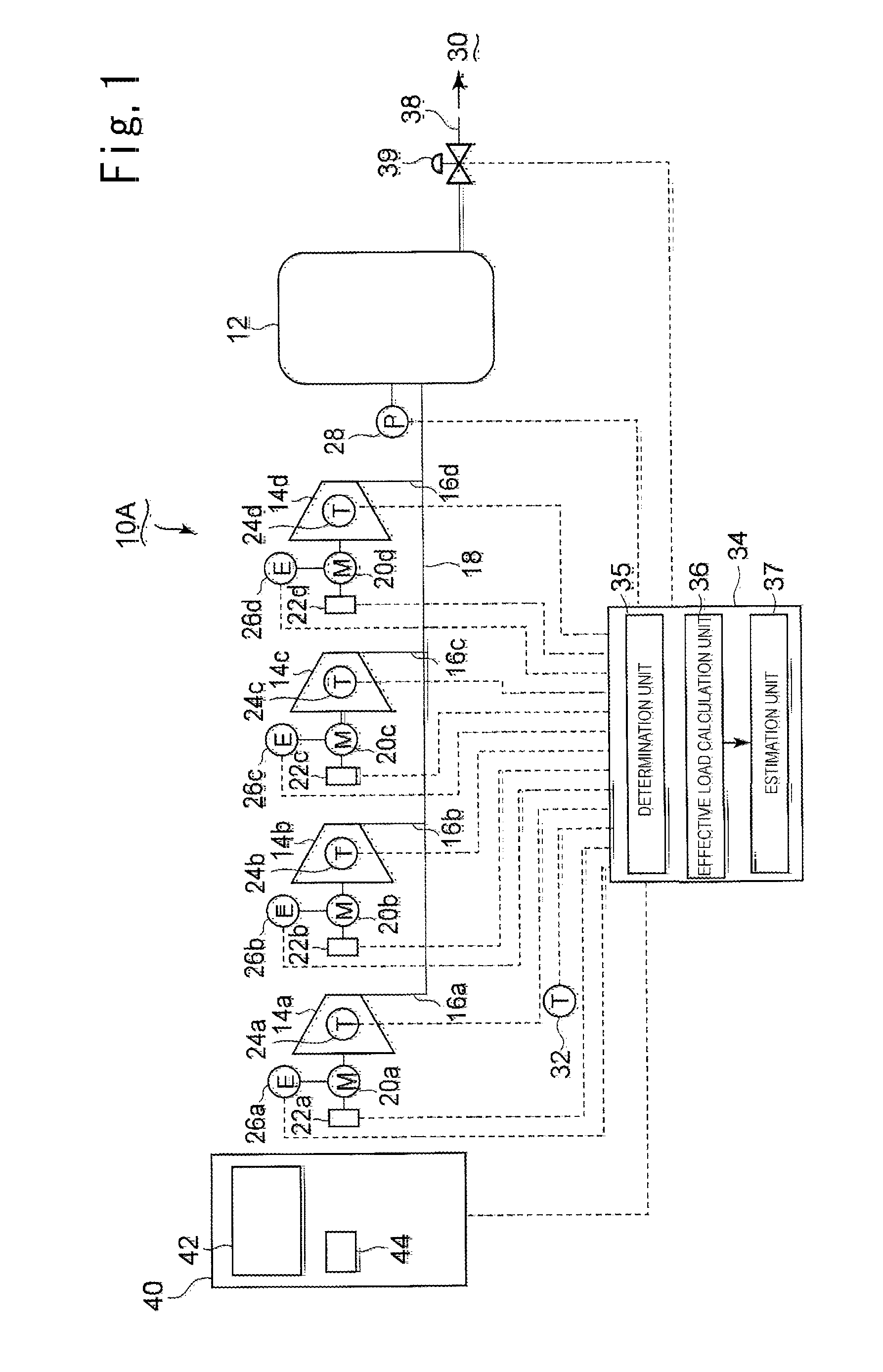
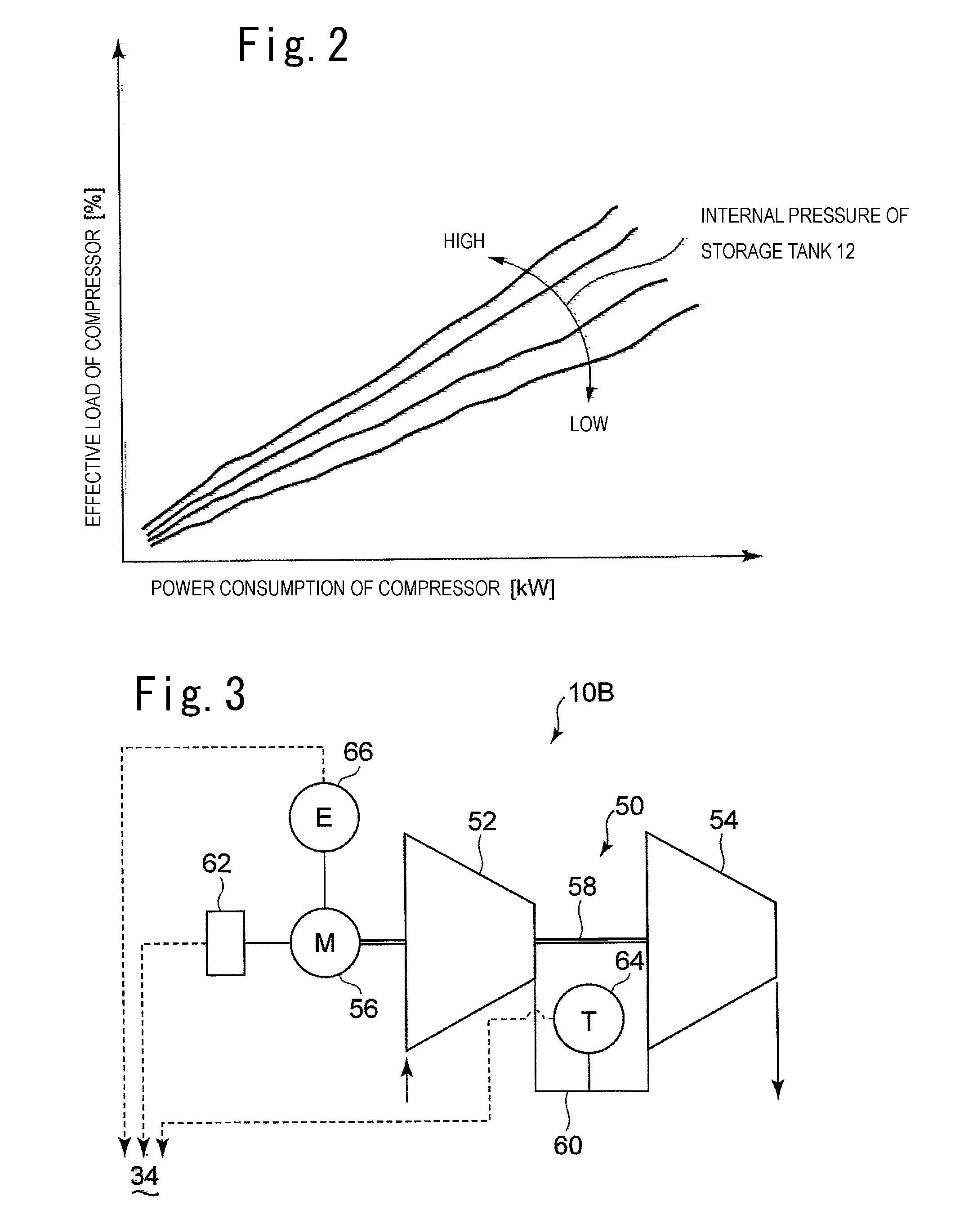
[0052]Next, a second embodiment of each of the apparatus of the first aspect of the present invention and the method of the first aspect of the present invention will be described with reference to FIG. 3. A two-stage compressor 50 constituting a compressed gas supply unit 10B of the present embodiment includes a low-pressure side compressor 52 and a high-pressure side compressor 54. That is, the low-pressure side compressor 52 and the high-pressure side compressor 54 are driven by a shared rotating shaft 58, and the rotating shaft 58 is driven by a drive motor 56. Gas discharged from the low-pressure side compressor 52 is supplied to the high-pressure side compressor 54 via an intermediate discharge path 60, further compressed in the high-pressure side compressor 54, and sent to the storage tank (not shown). The RPM of the drive motor 56 can be steplessly adjusted by an inverter 62.

[0053]The intermediate discharge path 60 is provided with a temperature sensor 64 which detects the t...

third embodiment

[0056]Next, an embodiment of each of an apparatus of a second aspect of the present invention and a method of a second aspect of the present invention will be described with reference to FIG. 4. A compressed gas supply apparatus 70 of the present embodiment includes a plurality of compressed gas supply units 10A, 10B, and 10C provided at positions apart from each other and a central control unit 72 which can remotely control the compressed gas supply units. Each of the compressed gas supply units 10A and 10C has the same configuration as that of the compressed gas supply unit 10A of the first embodiment, and the compressed gas supply unit 10B has the same configuration as that of the compressed gas supply unit 10B of the second embodiment.

[0057]The compressed gas supply unit 10A and the central control unit 72 are provided with transmitter-receivers 74 and 80 respectively. The compressed gas supply unit 10A and the central control unit 72 can perform data communication therebetween ...


PUM


Abstract

A compressed gas supply unit includes compressors. Gas discharged from the compressors is stored in a storage tank and then supplied to a gas recipient. The pressure of the storage tank, the operation temperature and the power consumption of each compressor, and the temperature around the compressors are sent to a controller and a monitoring device. A determination unit of the controller determines the presence or absence of the abnormality of the compressor from a difference between the operation temperature of the compressor and the temperature around the compressors. An effective load calculation unit calculates the effective load of each compressor from the power consumption of the compressor and the pressure of the storage tank. The controller controls the compressors based on the calculated effective load such that the loads of the compressors are equalized. An estimation unit estimates maintenance timing from the effective load.

Description

BACKGROUND OF THE INVENTION[0001]1. Field of the Invention[0002]The present invention relates to a compressed gas supply unit which includes a plurality of compressors and allows the energy-saving operation of the compressors and saving of a maintenance cost, a compressed gas supply apparatus, and a control method of the unit and the apparatus.[0003]2. Description of the Related Art[0004]There is known a compressed gas supply unit which includes a plurality of compressors and supplies compressed gas to a gas recipient while controlling the number of compressors under operating condition according to a demand. In such a compressed gas supply unit, energy saving is achieved by minimizing the number of compressors under operating condition. Japanese Patent Application Laid-open No. 2010-190197 discloses a compressed gas supply unit which includes a shared storage tank which stores gas discharged from a plurality of compressor and a pressure sensor which detects the internal pressure of...

Claims


Application Information

Patent Timeline
Patent Type & Authority Applications(United States)
IPC IPC(8): F04D27/00
CPCF04D27/00F04D27/001F04D27/0269
Inventor FUJIOKA, TAMOTSUUNAMI, ATSUSHIMATSUZAKI, KENJI
Owner ANEST IWATA CORP
Why Eureka
Try Eureka