
Multi-band multi-path receiving and transmitting device and method, and base station system

a multi-path and receiving and transmitting technology, applied in the field of mobile communication technology, can solve the problems of multi-frequency combiner, increase the material cost and mounting cost of the base station system, reduce etc., and achieve the reduction of the loss of received signal and transmitted signal, the effect of improving the coverage performance of the base station

Active Publication Date: 2013-10-17
HUAWEI TECH CO LTD
View PDF10 Cites 2 Cited by
  • Summary
  • Abstract
  • Description
  • Claims
  • Application Information

AI Technical Summary

Benefits of technology

[0005]Accordingly, embodiments of the present invention are directed to a multi-band multi-path receiving and transmitting device and method, and a base station system, to improve the coverage performance of a base station, and reduce the material cost and the mounting cost of a base station system.
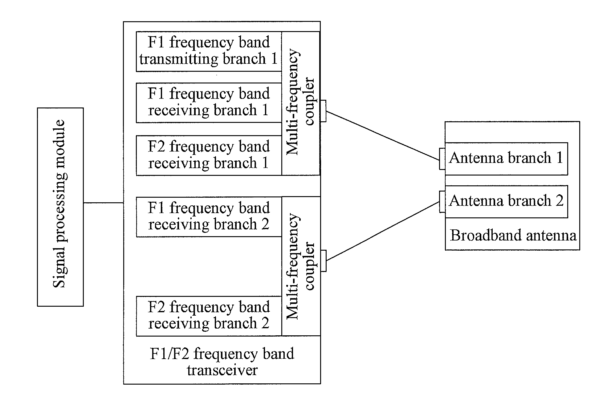
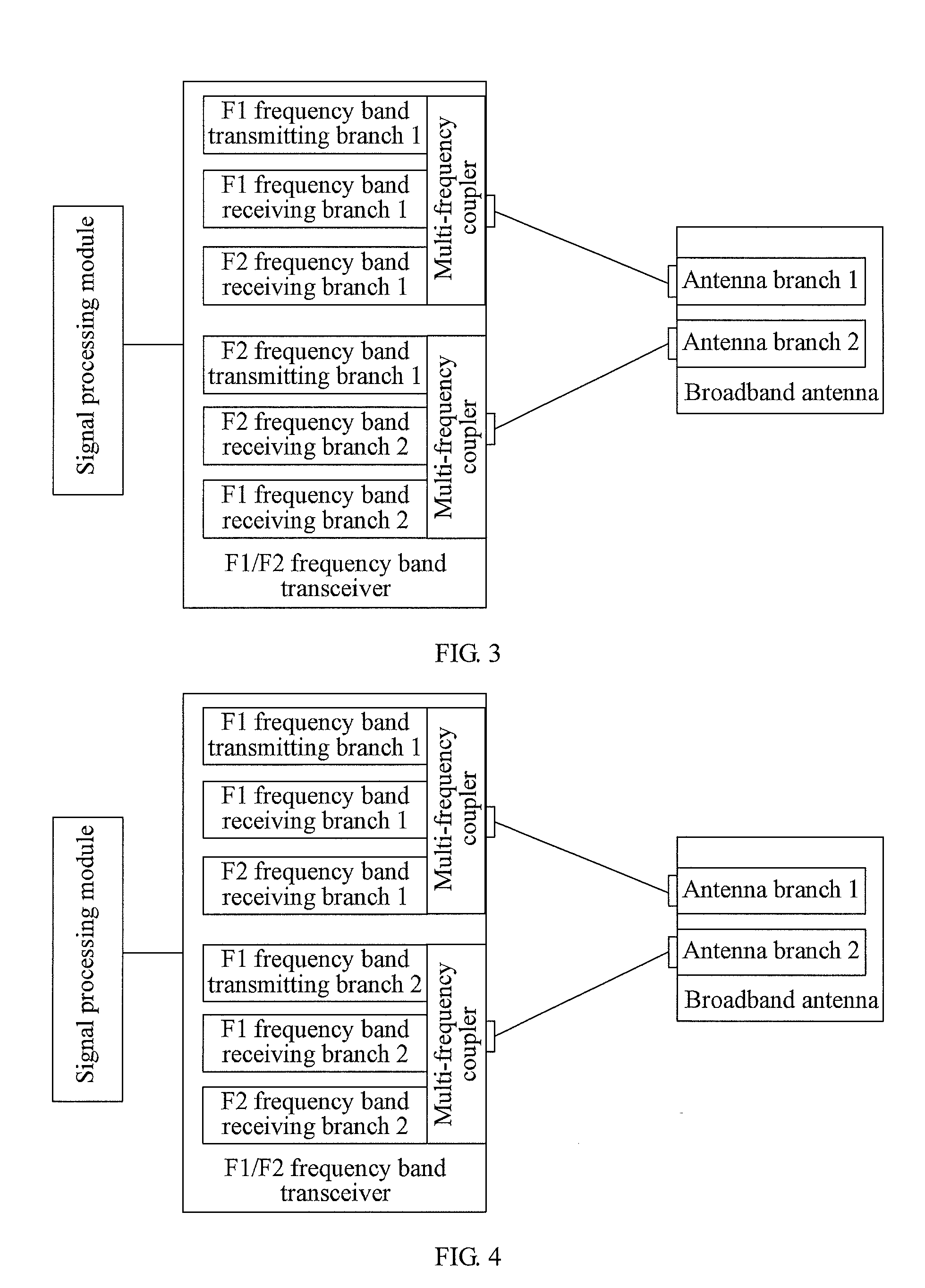
[0031]It can be known from the technical solutions that, according to the embodiments of the present invention, the multi-band transceiver is adopted to decrease the number of the transceivers, thereby reducing the material cost and the mounting cost of the base station system. Alternatively, according to the embodiments of the present invention, by building the multi-frequency coupler in one single-band transceiver, only a small number of jumpers need to be connected with the receiving branch of another single-band transceiver, so that the loss of the received signal and the transmitted signal is reduced, thereby improving the coverage performance of the base station. Meanwhile, the multi-frequency coupler is built in the multi-band transceiver or the single-band transceiver, to further reduce the material cost and the mounting cost of the base station system.

Problems solved by technology

In the prior art, more frequency bands need more single-band transceivers, which increases the material cost and the mounting cost of the base station system; and the jumper between the external multi-frequency combiner and the single-band transceiver increases signal loss, which results in the reduction of the coverage performance of the base station.
Additionally, the external multi-frequency combiner also increases the material cost and the mounting cost of the base station system.

Method used


Image

  • Multi-band multi-path receiving and transmitting device and method, and base station system
  • Multi-band multi-path receiving and transmitting device and method, and base station system
  • Multi-band multi-path receiving and transmitting device and method, and base station system

Examples


embodiment 1

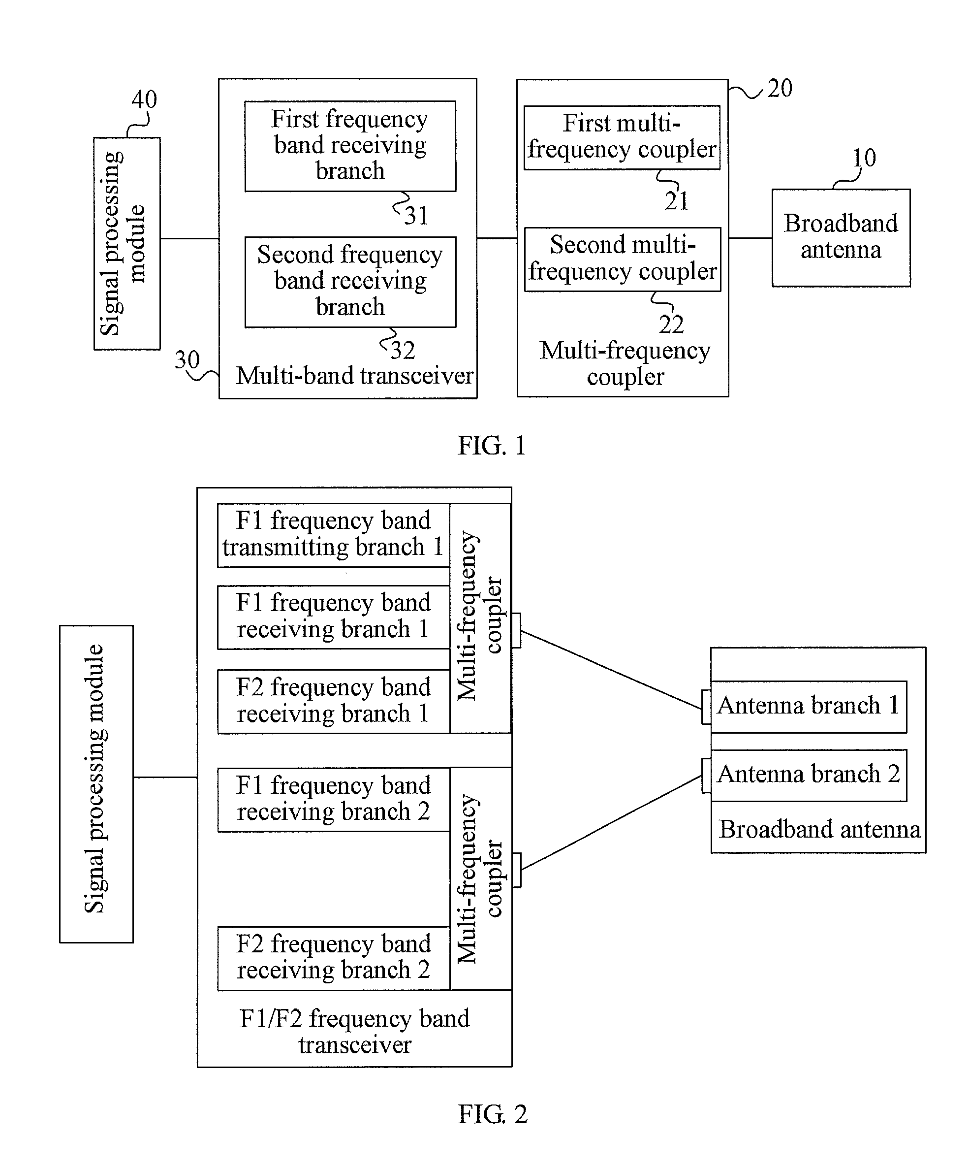
[0048]FIG. 1 is a schematic structural view of a multi-band multi-path receiving and transmitting device of the present invention. As shown in FIG. 1, the multi-band multi-path receiving and transmitting device of this embodiment includes a broadband antenna 10; at least two multi-frequency couplers 20, including a first multi-frequency coupler 21 and a second multi-frequency coupler 22; a multi-band transceiver 30, including at least two first frequency band receiving branches 31 and at least two second frequency band receiving branches 32; and a signal processing module 40.

[0049]The broadband antenna 10 is configured to receive at least a first frequency band signal and a second frequency band signal, and send the first frequency band signal and the second frequency band signal to the at least two multi-frequency couplers 20.

[0050]The first multi-frequency coupler 21 is configured to receive the first frequency band signal and the second frequency band signal sent by the broadban...

embodiment 2

[0092]FIG. 9 is a schematic structural view of another multi-band multi-path receiving and transmitting device of the present invention. As shown in FIG, 9, the multi-band multi-path receiving and transmitting device of this embodiment includes a broadband antenna 50; at least two multi-frequency couplers 60, including a first multi-frequency coupler 61 and a second multi-frequency coupler 62; two multi-band transceivers 70, including a first multi-band transceiver 71 and a second multi-band transceiver 72; and a signal processing module 80.

[0093]The broadband antenna 50 is configured to receive at least a first frequency band signal and a second frequency band signal, and send the first frequency band signal and the second frequency band signal to the at least two multi-frequency couplers 60.

[0094]The first multi-frequency coupler 61 is configured to receive the first frequency band signal and the second frequency band signal sent by the broadband antenna 50, and send the first fr...

embodiment 3

[0103]FIG. 10 is a schematic structural view of yet another multi-band multi-path receiving and transmitting device of the present invention. As shown in FIG. 10, the multi-band multi-path receiving and transmitting device of this embodiment includes a broadband antenna 120; at least two multi-frequency couplers 90, including a first multi-frequency coupler 91 and a second multi-frequency coupler 92; at least two single-band transceivers 100, including a first frequency band transceiver 101 and a second frequency band transceiver 102, in which the first multi-frequency coupler 91 is built in the first frequency band transceiver 101, and the second multi-frequency coupler 92 is built in the second frequency band transceiver 102; and a signal processing module 110.

[0104]The broadband antenna 120 is configured to receive at least a first frequency band signal and a second frequency band signal, and send the first frequency band signal and the second frequency band signal to the at lea...


PUM


Abstract

A multi-band multi-path receiving and transmitting device and method, and a base station system are provided. The multi-band multi-path receiving and transmitting device includes a broadband antenna, at least two multi-frequency couplers, a multi-band transceiver, and a signal processing module. The multi-band transceiver is adopted to decrease the number of the transceivers, thereby reducing the material cost and the mounting cost of the base station system.

Description

CROSS-REFERENCE TO RELATED APPLICATIONS[0001]This application is a continuation of International Application No. PCT / CN2011 / 070345, filed on Jan. 18, 2011, which claims priority to Chinese Patent Application No. 201010590971.8, filed on Dec. 15, 2010, both of which are hereby incorporated by reference in their entireties.FIELD OF THE INVENTION[0002]The present invention relates to a mobile communication technology, and in particular, to a multi-band multi-path receiving and transmitting device and method, and a base station system.BACKGROUND OF THE INVENTION[0003]In the field of mobile communications, since capacity demands are continuously expanded, a plurality of frequency band transceivers works simultaneously for one base station system; meanwhile, with the development of antenna technologies, frequency bands supported by antennas are also continuously extended, and currently the antennas can support 790 MHz to 960 MHz or 1710 MHz to 2690 MHz. when realizing multi-band multi-pat...

Claims


Application Information

Patent Timeline
Patent Type & Authority Applications(United States)
IPC IPC(8): H04B1/00
CPCH04B1/005H04B1/0057H04B1/50H04B1/40
Inventor WU, WANGJUNLI, YULINYAN, FENGQINGZHANG, XIAODONGZHANG, XIWEN
Owner HUAWEI TECH CO LTD
Learn More