Drive device for a motor vehicle

a technology for driving devices and motor vehicles, applied in the direction of electric propulsion mounting, transportation and packaging, gearing, etc., can solve the problem that the drive device requires especially little installation space, and achieve the effect of small installation space, effective and efficient torque conversion, and small space requiremen

Inactive Publication Date: 2013-10-17
SIEMENS AG
View PDF23 Cites 12 Cited by
  • Summary
  • Abstract
  • Description
  • Claims
  • Application Information

AI Technical Summary

Benefits of technology

[0030]According to another advantageous feature of the invention, the differential gear can be constructed as a bevel differential gear. This means that balance wheels of the differential gear are bevel wheels, so that the differential gear and thus the drive device have a very small space requirement.
[0031]When installed into a vehicle, a drive device according to the invention makes it possible to route the drive shafts, which are driven via the differential gear and via which the wheels of the vehicle are driven, directly, i.e. without diversions, to respective axial machine sides, i.e. at the respective axial ends of the electric machine. In other words the torque output via the differential gear and transmitted to the drive shaft will be routed directly to the driven wheels, without at least one further transmission stage and thus a further conversion of the torque being provided in the flow of force and / or torque from the differential gear to the wheels. Such an additional transmission stage can be dispensed with since a drive device according to the invention enables an effective and efficient conversion of the torque provided by the electric machine in a very small installation space. To this end the single or multi-stage transmission device as well as any differential gear that may be provided is integrated into the rotor element for ideal and direct distribution of the torque or the force and / or torque flow at least essentially from the axial center of the rotor elements to the drive shaft.

Problems solved by technology

Thus, the drive device requires especially little installation space.

Method used


Image

  • Drive device for a motor vehicle
  • Drive device for a motor vehicle

Examples


Embodiment Construction

[0035]The depicted embodiment is to be understood as illustrative of the invention and not as limiting in any way. It should also be understood that the figure is not necessarily to scale and that the embodiment may be illustrated by graphic symbols, phantom lines, diagrammatic representations and fragmentary views. In certain instances, details which are not necessary for an understanding of the present invention or which render other details difficult to perceive may have been omitted. The features and combinations of features specified in the description as well as the features and combinations of features specified in the description of the FIGURE and / or in the FIGURE alone are able to be used not only in the respectively specified combination, but also in other combinations or on their own, without departing from the framework of the invention.

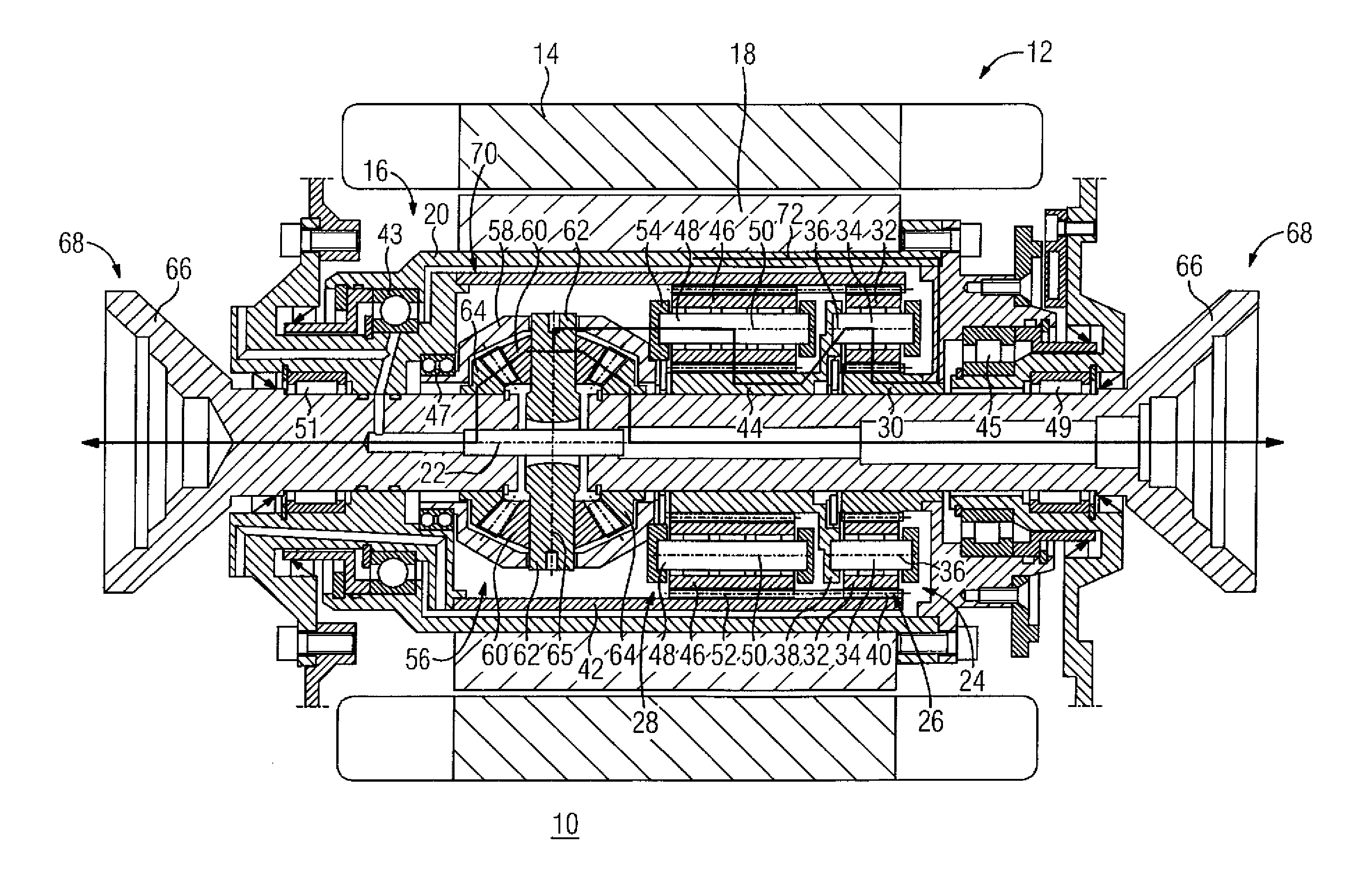
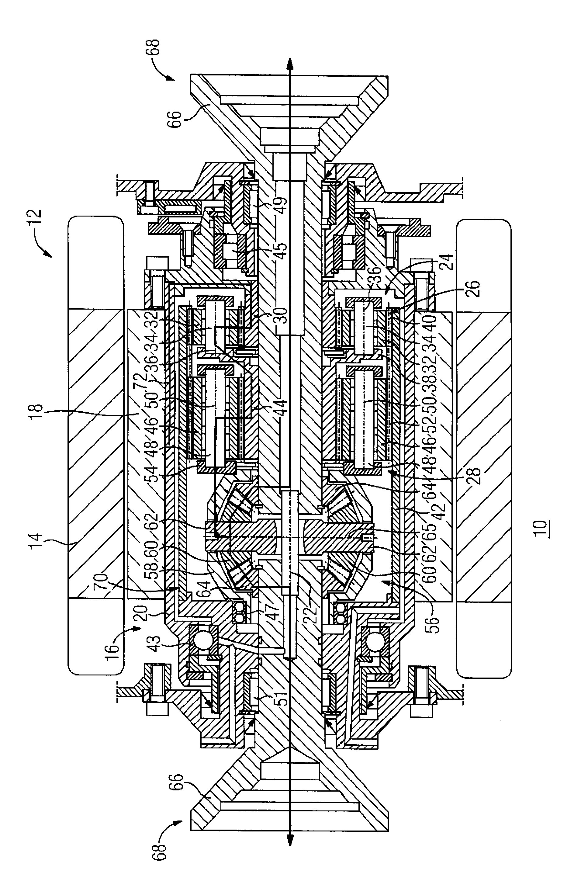
[0036]Turning now to the FIGURE, there is shown a schematic longitudinal sectional view of a drive device for a motor vehicle embodied f...


PUM


Abstract

A drive device for a vehicle includes at least one electric machine having at least one rotor element which is configured to delimit an installation area in a radial direction. Disposed, at least partly, in the installation area, is at least one transmission device which is configured to be driven by the electric machine via the rotor element.

Description

CROSS-REFERENCES TO RELATED APPLICATIONS[0001]This application claims the priority of German Patent Application, Ser. No. 10 2012 206 142.8, filed Apr. 16, 2012, pursuant to 35 U.S.C. 119(a)-(d), the content of which is incorporated herein by reference in its entirety as if fully set forth herein.BACKGROUND OF THE INVENTION[0002]The present invention relates to a drive device for a motor vehicle.[0003]The following discussion of related art is provided to assist the reader in understanding the advantages of the invention, and is not to be construed as an admission that this related art is prior art to this invention.[0004]Electric and hybrid vehicles which are able to be driven by at least one electric motor via a corresponding drive device of the motor vehicle are known from the prior art as well as from series production of motor vehicles, especially of automobiles. In such motor vehicles, wheels of the vehicle are driven by an electric motor via corresponding drive shafts.[0005]A...

Claims


Application Information

Patent Timeline
Patent Type & Authority Applications(United States)
IPC IPC(8): F16H3/44F16H48/06
CPCF16H3/44F16H48/06F16H1/46F16H48/08H02K7/116H02K7/006B60K2001/001
Inventor KALMBACH, KLAUSSCHLEICHER, KLAUSSTEINZ, JANINA
Owner SIEMENS AG
Why Eureka
Try Eureka