Suture anchor and method for attaching soft tissue to bone
What is Al technical title?
Al technical title is built by PatSnap Al team. It summarizes the technical point description of the patent document.
a technology of soft tissue and bone, which is applied in the field of suture anchors and methods for attaching soft tissue to bone, can solve the problems of affecting the application of sutures, affecting the healing effect of soft tissue,
Active Publication Date: 2013-10-17
VYHMEISTER EDWIN D
View PDF6 Cites 2 Cited by
Summary
Abstract
Description
Claims
Application Information
AI Technical Summary
This helps you quickly interpret patents by identifying the three key elements:
Problems solved by technology
Method used
Benefits of technology
[0013]It is therefore an object of the present invention to prov
Problems solved by technology
This design has the disadvantage of potential trauma and damage to the bone and surrounding tissues.
This type also has the possibility that it could come loose and it has limited applications due to the increased access that is required to apply the impacting forces to fix the anchor to the bone.
Another disadvantage of this type of anchor is that it is only suited to larger bone because sometimes smaller bone and surrounding or attached tissues cannot handle the impact forces required to set this type of anchor into place.
The hammered in type of anchor is also associated with high costs and increased difficulty removing them in the future if the need arises.
Other disadvantages of this type of anchor is that special tools are also required to set them in place, they are time consuming to install and they require a larger hole or bone tunnel to be used which can weaken the bone.
The screw insertion method has disadvantages because it tends to be time consuming, very costly and typically requires specialized high priced tools to use.
Another disadvantage of the screw in anchor is that many screw in designs require the bone tunnel hole to be larger and tapped to receive the screw in anchor.
The larger hole, the tapping and or insertion of the screw can weaken the bone and cause additional damages to surrounding tissues and take more time to install.
The screw in anchor design also has the disadvantage of being very high priced as compared to some other suture anchor designs.
Drilling extra holes to accommodate the anchor or tools to install the anchor are disadvantages because the extra hole can weaken the bone and the installation process takes longer and is more complicated plus this
Method used
Image
Click on the blue label to locate the original text in one second.
Reading with bidirectional positioning of images and text.
Examples
Embodiment Construction
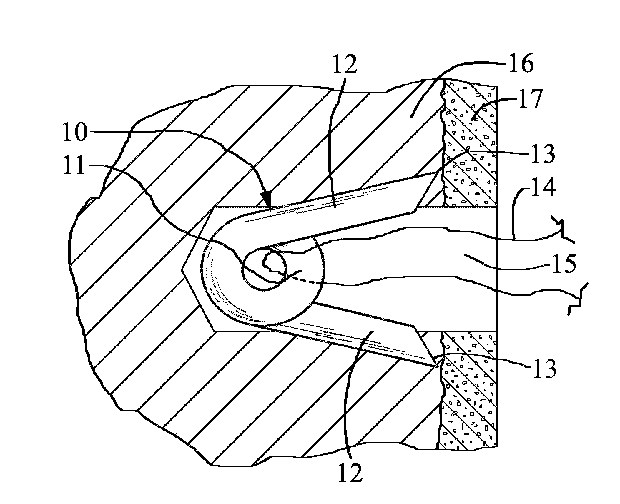
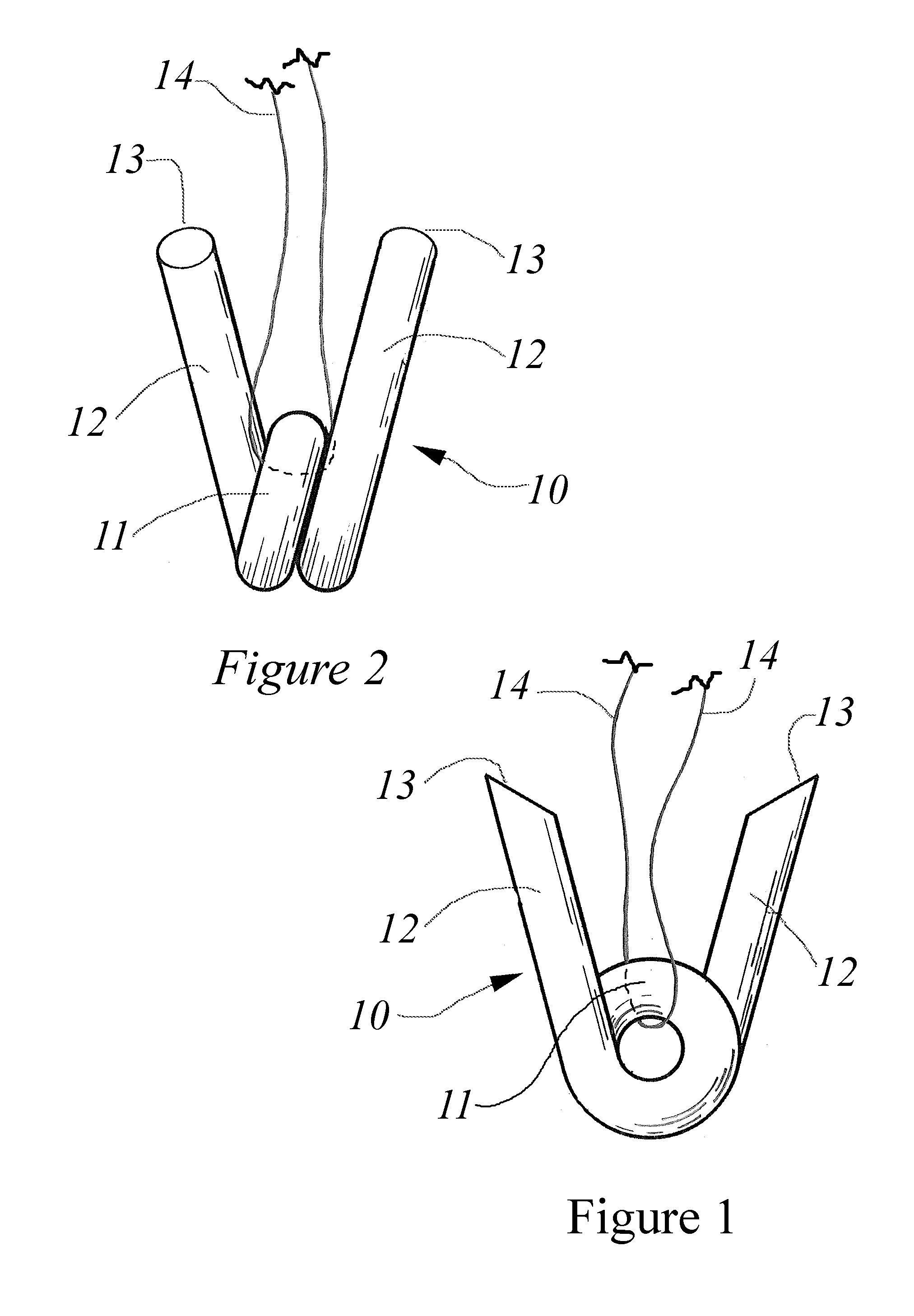
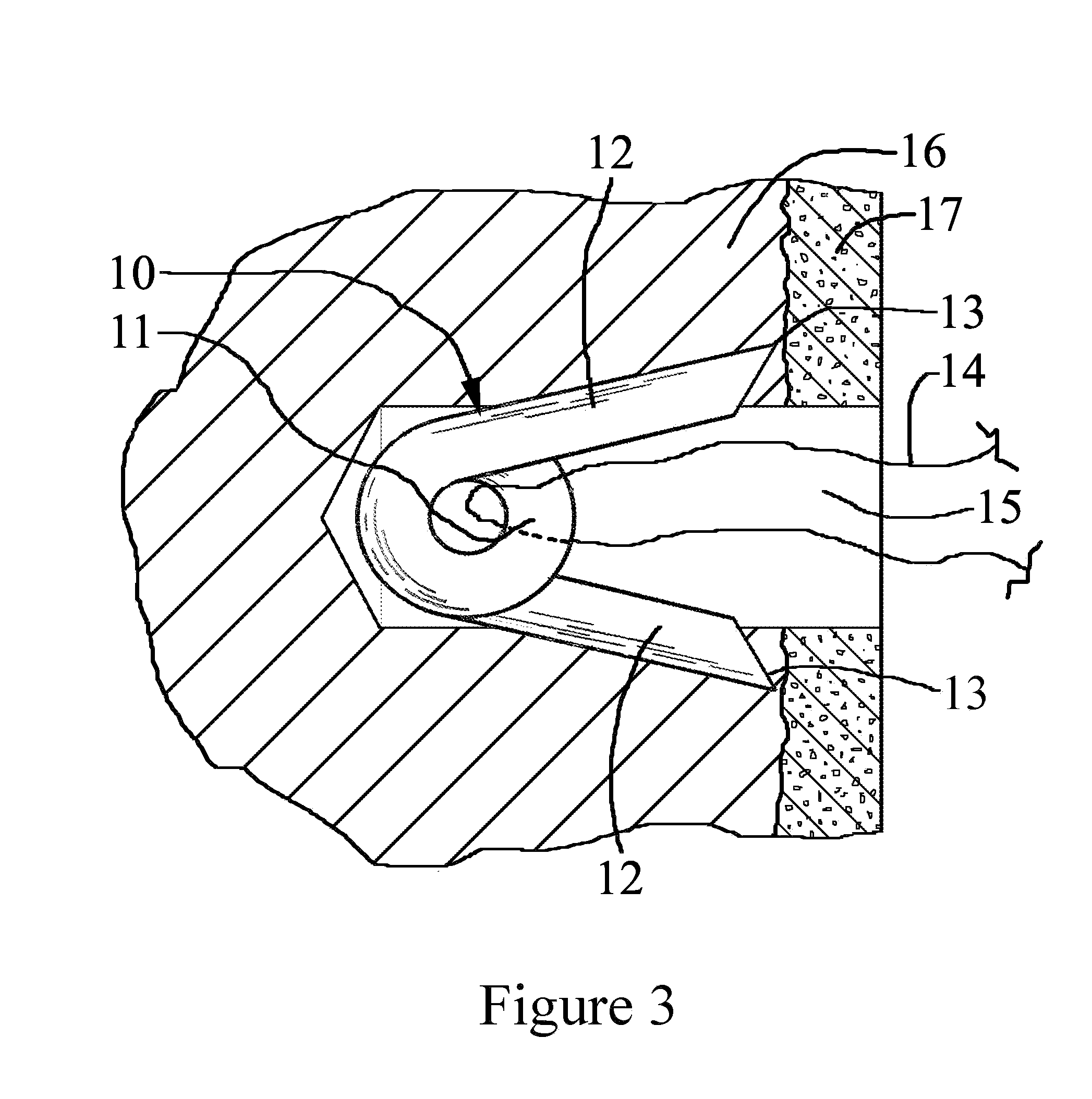
[0028]Referring specifically to FIGS. 1, 2 and 3, a resiliently flexible wire is bent and twisted to form a suture anchor 10 with a suture retaining loop 11 positioned at the center of a precisely measured and cut length of wire. The suture loop 11 constitutes the proximal end of the anchor device 10 and in the preferred embodiment has a helical shape that provides spring flexibility to the two wire ends that make up the two diverging legs 12. In the illustrated embodiment the wire forms approximately one and three quarters helical loops 11 with the ends of the wire extending away from the loop to make two legs 12 diverging at a desired angle of between 30 degrees to 45 degrees depending on the anchors intended use. The two legs 12, when unconstrained, have their pointed ends 13 spaced at a distance that is greater that the diameter of the bone tunnel 15 that has been drilled into the bone 16 to which the suture anchor is to be deployed. The suture 14 is passed through the suture re...
PUM
Abstract
A suture anchor made of a single length of resilient wire bent to form a suture retaining loop disposed proximally between two diverging legs with pointed ends sharing an independent plane. The anchor is to be inserted suture retaining loop first into a bone tunnel having a diameter equal to the diameter of the suture retaining loop but smaller than the transverse spacing of the distal points of the static uncompressed legs. The two diverging coplanar legs extend radially till the distal points are set wider than the diameter of the bone tunnel so that when the anchor is inserted into the bone tunnel the static uncompressed legs compress together to penetrate into the bone tunnel. Once the anchor is set deep enough into the hole so that the distal points of each leg are below the surface of the bone cortex the sharp distal points of each leg expand out under pressure and penetrate the tunnel wall prohibiting removal of the anchor and penetrate the tunnel wall in response to applied withdrawal forces. Spring loading of the resilient wire allows for lateral expansion of the two diverging legs inside of the soft bone tunnel and the tension or pulling on the suture sets the distal tip of each leg into the inner surface of the bone cortex.
Description
REFERENCES CITED[0001]US Patent Documents;4,741,330May 1988Hayhurst4,899,743February 1990Nicholson et al.4,968,315November 1990Gatturna5,102,421April 1992Anspach, Jr.5,141,520August 1992Goble et al.5,156,616October 1992Meadows et al.5,501,696March 1996Trott8,137,383March 2012West, Jr. et al.5,944,724August 1999Lizardi7,645,293January 1910Martinek et al.RELATED APPLICATION[0002]This application claims the priority of, and hereby incorporates by reference, provisional application Ser. No. 61 / 622,822 filed Apr. 11, 2012. All of the foregoing patent disclosures are fully incorporated herein by reference.BACKGROUND OF THE INVENTION[0003]1. Technical Field[0004]This invention pertains to the methods and apparatus utilized in surgical procedures involving the fixation of soft tissue to bone tissue and in particular to a novel method and apparatus for anchoring sutures to bone[0005]2. Discussion of the Prior Art[0006]As a common procedure of various surgeries, open, arthroscopic or endoscop...
Claims
Application Information
Patent Timeline
Application Date:The date an application was filed.
Publication Date:The date a patent or application was officially published.
First Publication Date:The earliest publication date of a patent with the same application number.
Issue Date:Publication date of the patent grant document.
PCT Entry Date:The Entry date of PCT National Phase.
Estimated Expiry Date:The statutory expiry date of a patent right according to the Patent Law, and it is the longest term of protection that the patent right can achieve without the termination of the patent right due to other reasons(Term extension factor has been taken into account ).
Invalid Date:Actual expiry date is based on effective date or publication date of legal transaction data of invalid patent.