Partitioned distributor tray for offshore gas/liquid contact column

Active Publication Date: 2013-10-24
INST FR DU PETROLE
View PDF13 Cites 34 Cited by
  • Summary
  • Abstract
  • Description
  • Claims
  • Application Information

AI Technical Summary

Problems solved by technology

Under such conditions, the operation of conventional distributor trays equipped with chimneys (FIG. 2) can be greatly disturbed.
When tray (2) is inclined under the effect of the wave motion (FIG. 3), the height of the liquid level is no longer uniform on the distributor tray (h1>h2), which causes an imbalance in the distribution of liquid at the inlet of gas/liquid contactor (3).
The distribution quality and thus the efficiency of the column are greatly impacted.
This poor distribution, if it is not controlled, can substantially degrade the pe

Method used


Image

  • Partitioned distributor tray for offshore gas/liquid contact column
  • Partitioned distributor tray for offshore gas/liquid contact column
  • Partitioned distributor tray for offshore gas/liquid contact column

Examples


example 1

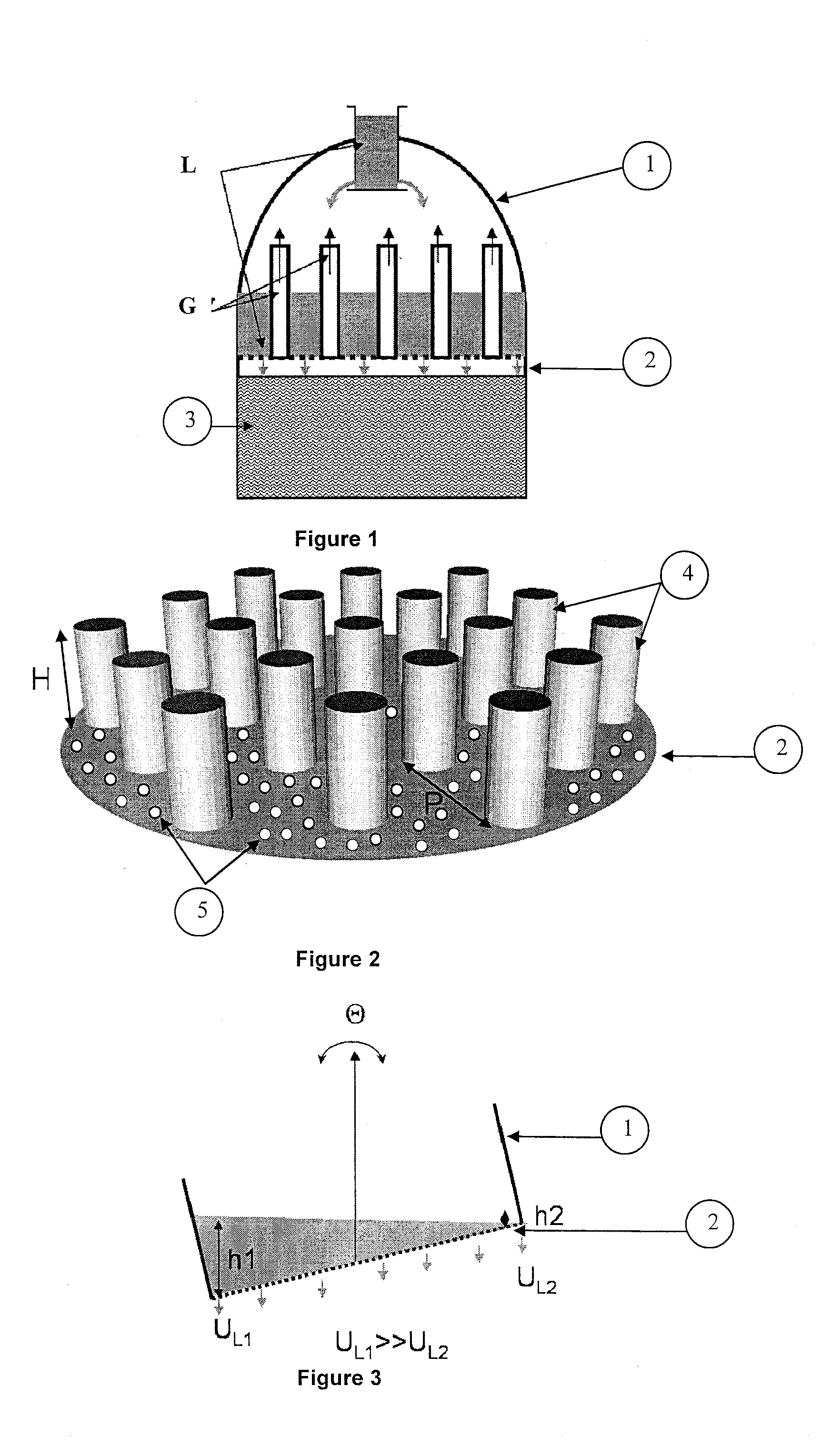
Properties of the “Conventional” Tray (Prior Art of FIG. 2)

[0099]The diameter of the distributor tray is 4150 mm.

[0100]The diameter of the gas chimneys is 350 mm.

[0101]The height of the gas chimneys is 700 mm.

[0102]The triangular pitch P of the gas chimneys is 200 mm.

[0103]The minimum distance to the edge of the gas chimneys is 100 mm.

[0104]The number of chimneys is 19.

[0105]The tray porosity (chimney surface area / total surface area) is 13.5.

example 2

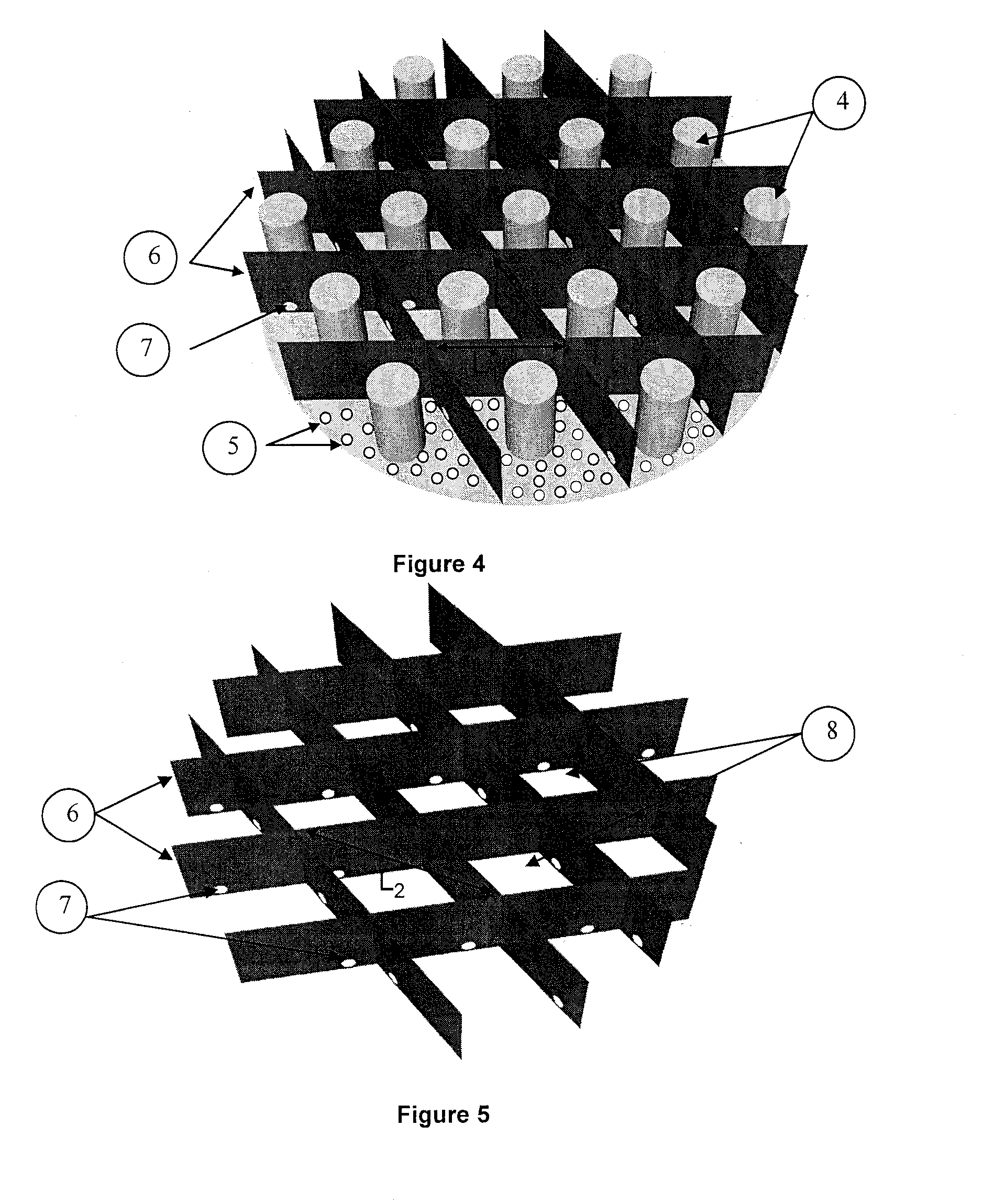
Properties of the Tray According to the Invention (FIG. 4)

[0106]The diameter of distributor tray (2) is 4150 mm.

[0107]The diameter of gas chimneys (4) is 350 mm.

[0108]The height of gas chimneys (4) is 700 mm.

[0109]The triangular pitch P of gas chimneys (4) is 200 mm.

[0110]The minimum distance to the edge of chimneys (4) is 100 mm.

[0111]The number of chimneys (4) is 19.

[0112]The tray porosity (chimney surface area / total surface area) is 13.5.

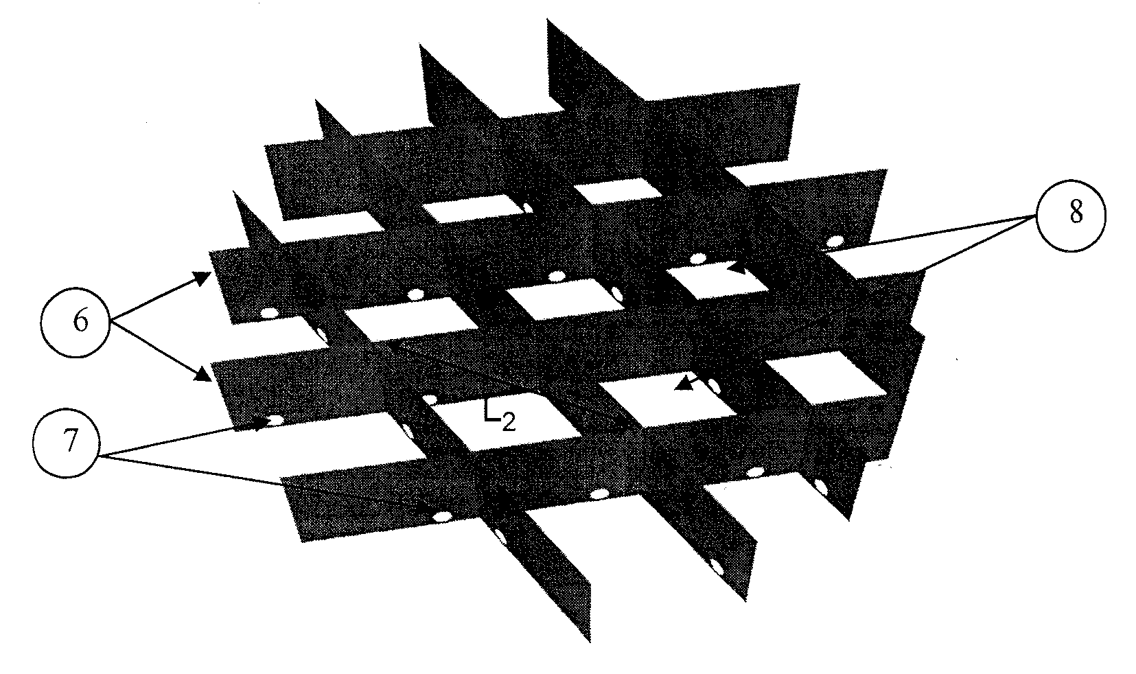
[0113]The height of partitioning means (6) is 700 mm.

[0114]The diameter of perforations (7) on partitioning means (6) is 50 mm.

[0115]The number of compartments (8) is 23 it can be noted that 4 truncated compartments arranged on the periphery of the tray contain no chimney as shown in FIG. 4.

[0116]The distance L1 is 920 mm.

[0117]The distance L2 is 1600 mm.

[0118]FIGS. 6 and 7 show the evolution of the liquid guard (gas / liquid interface) on the distributor when it is subjected to wave motions, for examples 1 and 2 respectively. The results are obtai...


PUM

PropertyMeasurementUnit
Lengthaaaaaaaaaa
Flow rateaaaaaaaaaa
Heightaaaaaaaaaa

Abstract

The invention is a distributor tray for a column (1) for heating and/or material exchange between a gas (G) and a liquid (L), comprising at least one wall (6) defining compartments (8) on one of the surfaces of the tray. The walls are perforated (7) to allow part of the liquid to flow between compartments (8). Each compartment comprise at least one means (5) providing passage of the liquid through the tray and at least one means providing passage of the gas through the tray. The invention also relates to a gas/liquid contact column, a gas treatment unit, a CO2 capture unit, a distillation unit, and an offshore floating barge comprising the distributor tray. The invention also relates to a method of manufacturing such a tray

Description

CROSS-REFERENCE TO RELATED APPLICATIONS[0001]Reference is made to French patent application Ser. No. 12 / 01.144, filed on Apr. 18, 2012, and copending related application entitled “DISTRIBUTOR TRAY FOR OFFSHORE GAS / LIQUID CONTACT COLUMN.” filed on Apr. 17, 2013 (Attorney Ref: 612.53034X00) which applications are incorporated herein by reference in their entirety.BACKGROUND OF THE INVENTION[0002]1. Field of the Invention[0003]The present invention relates to offshore gas / liquid contact columns, and more particularly to offshore gas treatment, CO2 capture, dehydration or distillation units.[0004]2. Description of the Prior Art[0005]Offshore gas treatment and / or CO2 capture units using amine wash processes comprise liquid or gaseous fluid absorption and regeneration columns. These columns operate under counter-current or co-current gas / liquid flow conditions and they are, for example, installed on vessels, floating barges or offshore platforms, of FPSO (Floating Production, Storage and ...

Claims


Application Information

Patent Timeline
IPC IPC(8): B01D53/18
CPCB01D53/185B01D3/008B63B35/44Y10T29/49
Inventor HAROUN, YACINERAYNAL, LUDOVICALIX, PASCAL
Owner INST FR DU PETROLE
Why Eureka
Try Eureka