Hybrid Induction Motor with Self Aligning Permanent Magnet Inner Rotor

a permanent magnet inner rotor, self-aligning technology, applied in the direction of dynamo-electric components, magnetic circuit shape/form/construction, dynamo-electric machines, etc., can solve the problems of low-power induction motors that are not highly efficient at designed operating speed, less efficient under reduced loads, and limited size of permanent magnets, so as to avoid magnetic overload and safely use ferrite magnets

Active Publication Date: 2013-10-24
MOTOR GENERATOR TECH INC
View PDF5 Cites 19 Cited by
  • Summary
  • Abstract
  • Description
  • Claims
  • Application Information

AI Technical Summary

Benefits of technology

[0012]In accordance with yet another aspect of the invention, there is provided a hybrid induction motor which is self regulating and avoids magnetic overload and stall if to much load is applied. As the motor approaches magnetic overload or stall, the permanent magnet rotor disengages from the inductive rotor and maintains synchronous RPM, The inductive and permanent magnet rotors re-couple whe

Problems solved by technology

Unfortunately, low power induction motors are not highly efficient at designed operating speed, and are even less efficient under reduced loads because the amount of power consumed by the stator remains constant at such reduced loads.

Method used


Image

  • Hybrid Induction Motor with Self Aligning Permanent Magnet Inner Rotor
  • Hybrid Induction Motor with Self Aligning Permanent Magnet Inner Rotor
  • Hybrid Induction Motor with Self Aligning Permanent Magnet Inner Rotor

Examples


sixth embodiment

[0105]A side view of a sixth motor 10f according to the present invention is shown in FIG. 53, an exploded side view of the sixth rotor 16f of the sixth motor 10f is shown in FIG. 54, a side view of the sixth inductive rotor 20f of the sixth motor 10f is shown in FIG. 55, a cross-sectional view of the sixth inductive rotor 20f of the sixth motor 10f taken along line 56-56 of FIG. 55 is shown in FIG. 56, a side view of a core laminate 31 is shown in FIG. 57 and a cross-sectional view of the core laminate 31 is shown in FIG. 58, a side view of the sixth permanent magnet rotor 26f of the sixth motor 10f is shown in FIG. 59A, an end view of the permanent magnet rotor 26f of the sixth motor 10f is shown in FIG. 59B, a perspective view of an inductive strip 23 for wrapping around the sixth permanent magnet rotor of the motor according to the present invention is shown in FIG. 60, and the inductive strip 23 unwrapped is shown in FIG. 61. The core laminate 31 is fixed to the motor shaft 32 ...

seventh embodiment

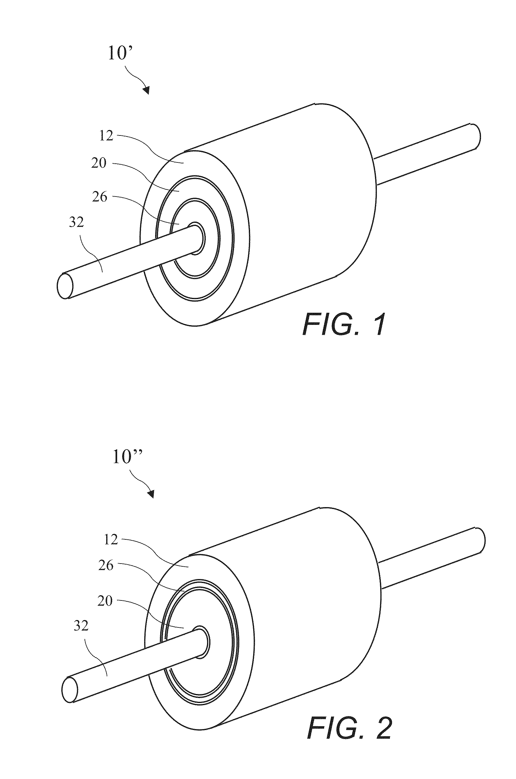
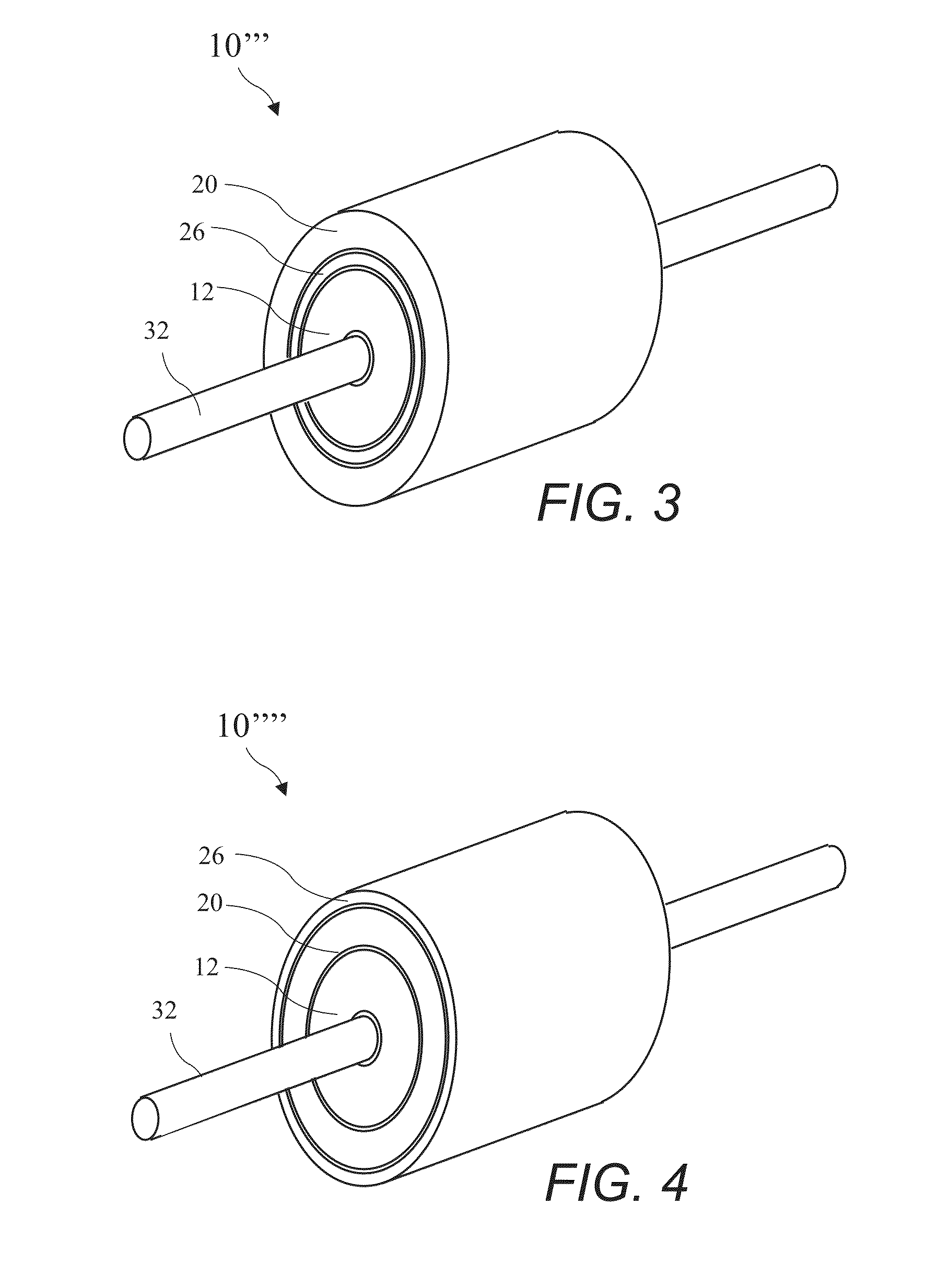
[0106]A side view of the motor 10g according to the present invention is shown in FIG. 62. The motor 10g includes a stator 12g, a permanent magnet rotor 26g, an inductive rotor 20g, cage rotor end rings 17g, and a clutch 34g. The permanent magnet rotor 26g is a ring magnet having a copper outer wrap.

eighth embodiment

[0107]A side view of the motor 10h according to the present invention is shown in FIG. 63. The motor 10h includes a stator 12h, a permanent magnet rotor 26h, an inductive rotor 20h, cage rotor end rings 17h, and a clutch 34h. The permanent magnet rotor 26h is a ring magnet having a copper inner wrap. The motor 10h has an internal stator 12h and the inductive rotor 20h and permanent magnet rotor 26h are outside the stator 12h. The clutch 34h is inside the cage rotor end rings 17h.


PUM


Abstract

A hybrid induction motor includes an inductive rotor and an independently rotating permanent magnet rotor. The inductive rotor is a squirrel cage type rotor for induction motor operation at startup. The permanent magnet rotor is axially displaced and variably coupled to the inductive rotor (or to a motor load) through a clutch and is allowed to rotate independently of the inductive rotor at startup. The independently rotating permanent magnet rotor quickly reaches synchronous RPM at startup. As the inductive rotor approaches or reaches synchronous RPM, the coupling between the inductive rotor and the permanent magnet rotor increases until the two rotors are coupled at the synchronous RPM and the motor transitions to efficient synchronous operation.

Description

CROSS-REFERENCE TO RELATED APPLICATIONS[0001]The present application is a Continuation In Part of U.S. patent application Ser. No. 13 / 452,514 filed Apr. 20, 2012, which application is incorporated in its entirety herein by reference.BACKGROUND OF THE INVENTION[0002]The present invention relates to electric motors and in particular to an induction motor having an independently rotating permanent magnet rotor variably coupled to an inductive rotor to reconfigure the motor from asynchronous induction operation at startup to synchronous operation after startup for efficient operation.[0003]A preferred form of electric motors are brushless AC induction motors. The rotors of induction motors include a cage (or squirrel cage resembling a “hamster wheel”) rotating inside a stator. The cage comprises axially running bars angularly spaced apart on the outer perimeter of the rotor. An AC current provided to the stator introduces a rotating stator magnetic field inside the rotor, and the rotati...

Claims


Application Information

Patent Timeline
IPC IPC(8): H02K21/46H02K7/108
CPCH02K21/46H02K7/108H02K16/02H02K17/26H02K1/22H02K21/12
Inventor FINKLE, LOUIS J.
Owner MOTOR GENERATOR TECH INC
Why Eureka
Try Eureka