Cornea imaging apparatus and cornea imaging method

a corneal imaging and corneal endothelium technology, applied in the field of corneal imaging apparatus and cornea imaging method, can solve the problems of significant deformation of endothelium imaging accuracy, imposed a significant burden on the tester and the test subject, and inability to obtain clear images of the corneal endothelium in some cases, so as to reduce the burden on the tester. , the effect of clear imag

Active Publication Date: 2013-10-24
TOMEY CORP
View PDF0 Cites 18 Cited by
  • Summary
  • Abstract
  • Description
  • Claims
  • Application Information

AI Technical Summary

Benefits of technology

[0039]According to the cornea imaging apparatus and the cornea imaging method following the present invention, the corneal endothelial cells can be imaged more clearly by means of aligning the imaging center axis of the imaging apparatus with the normal vector direction of the corneal endothelium. Also, changeable inclination angle of the im

Problems solved by technology

However, in the cornea imaging apparatus described in Japanese Patent No. 2580464, clear images of corneal endothelium could not be obtained in some cases since imaging of the corneal endothelium in the corneal periphery is performed through an XY alignment of the imaging optical system using specularly reflected light from the corneal epithelium (also called ectocornea) in the same way as for the center portion of the cornea.
However, under a state where the test subject fixates in an oblique direction to get images of the corneal periphery taken, the optical axis (marked with x) of the light reflected from the endothelium can be moved from the optical axis (marked with ) of the XY alignment light reflected f

Method used


Image

  • Cornea imaging apparatus and cornea imaging method
  • Cornea imaging apparatus and cornea imaging method
  • Cornea imaging apparatus and cornea imaging method

Examples


Embodiment Construction

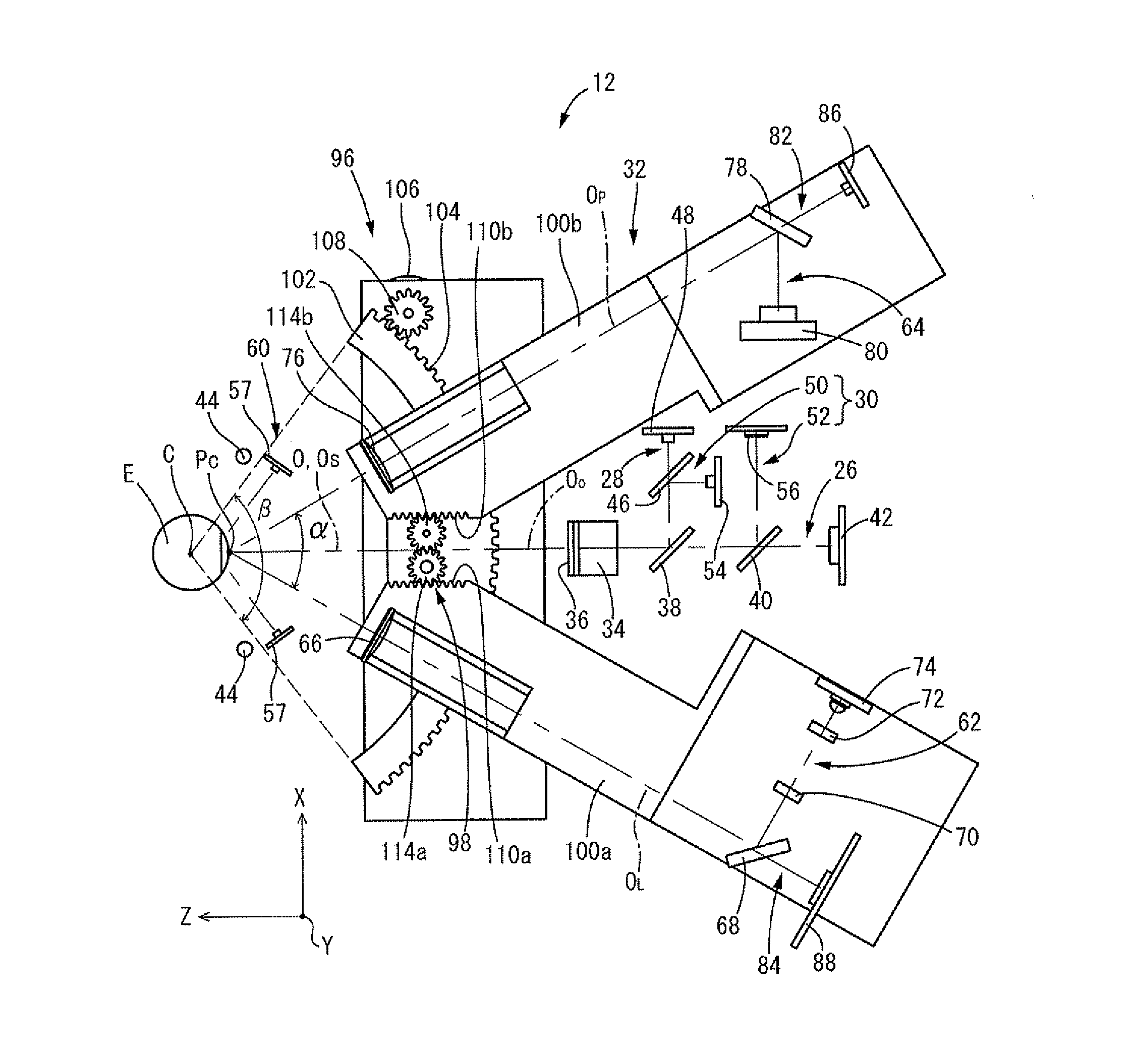
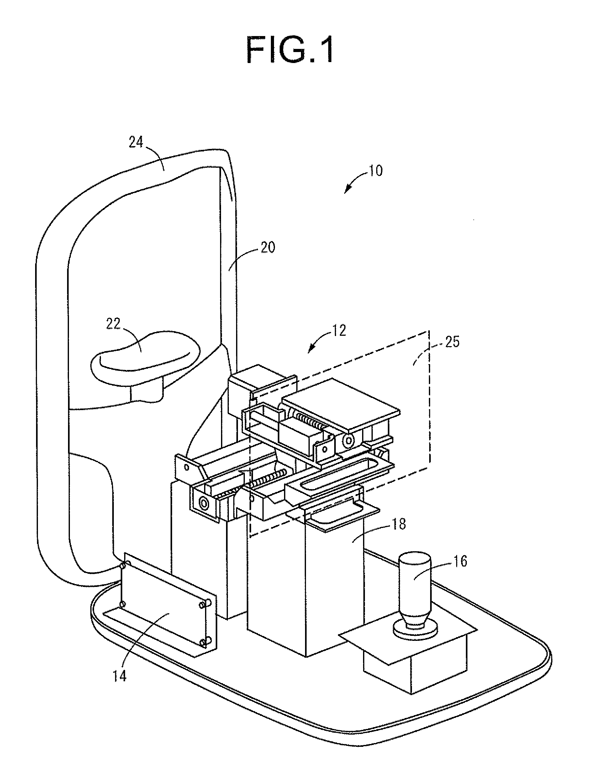
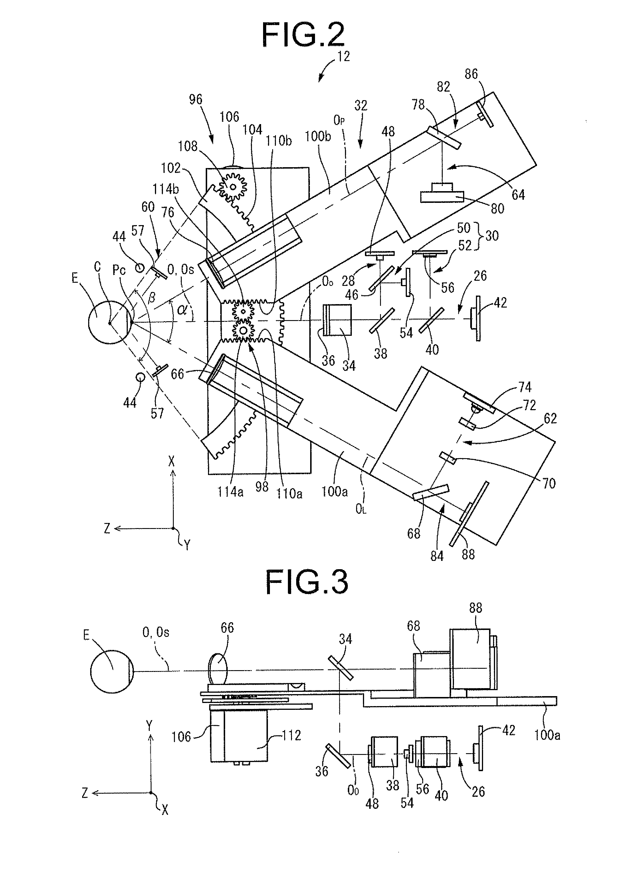
[0059]First, FIG. 1 schematically shows a cornea imaging apparatus 10 with the housing removed as a first embodiment of the present invention. The cornea imaging apparatus 10 is provided with an instrumental optical system 12, a control unit 14, an operation stick 16 and so forth. The instrumental optical system 12, arranged on a base 18 is movable thereon in three axial directions perpendicular to each other based on operations of the operation stick 16 and control instructions from the control unit 14. The cornea imaging apparatus 10 is also provided with a support table 20. The support table 20 is provided with a chin support 22 and a forehead pad 24 that fix the test subject's face looking toward the instrumental optical system 12 by having the test subject's chin on the chin support 22 and the forehead placed against the forehead pad 24. In addition, as shown schematically, the cornea imaging apparatus 10 is provided with a display monitor 25 made of a liquid crystal material a...


PUM


Abstract

A cornea imaging apparatus including: a collimation axis holding mechanism; an imaging mechanism; a Z-direction actuating means; an X-direction actuating means and a Y-direction actuating means; an inclination angle changing means that changes an inclination angle of an imaging center axis of the imaging mechanism against a collimation axis of an eye under examination; an endothelial configuration computing means that determines a corneal endothelial configuration; and a normal vector computing means that determines a normal vector direction at a given imaging position of the corneal endothelial configuration, wherein at the imaging position, the inclination angle and positions in the Z and X directions are set adjusted so as to align the imaging center axis of the imaging mechanism with the normal vector direction determined by the normal vector computing means.

Description

INCORPORATED BY REFERENCE[0001]The disclosure of Japanese Patent Application No. 2012-095408 filed on Apr. 19, 2012 including the specification, drawings and abstract is incorporated herein by reference in its entirety.BACKGROUND OF THE INVENTION[0002]1. Field of the Invention[0003]The present invention relates to a cornea imaging apparatus for imaging corneal endothelial cells by means of directing illumination light into an eye under examination and receiving light reflected from the cornea thereof, and a cornea imaging method.[0004]2. Description of the Related Art[0005]Conventionally, observation of the cornea of the eye, and in particular of the cellular status of the corneal endothelium, has been commonly carried out in determining a presence of ocular disorders or making a diagnosis of postoperative prognosis.[0006]In order to observe such cellular status of the corneal endothelium, there has been known a cornea imaging apparatus capable of imaging corneal endothelial cells w...

Claims


Application Information

Patent Timeline
IPC IPC(8): A61B3/15A61B3/10A61B3/107
CPCA61B3/152A61B3/107A61B3/1005A61B3/117A61B3/14
Inventor KATO, CHIHIRO
Owner TOMEY CORP
Why Eureka
Try Eureka