Surface profile measuring apparatus and method

a technology of surface profile and measuring apparatus, which is applied in the direction of measuring devices, instruments, and using optical means, can solve the problems of optical interference and increase in measurement time, and achieve the effect of wide measurement range and high speed

Inactive Publication Date: 2013-10-24
PANASONIC INTELLECTUAL PROPERTY MANAGEMENT CO LTD
View PDF0 Cites 13 Cited by
  • Summary
  • Abstract
  • Description
  • Claims
  • Application Information

AI Technical Summary

Benefits of technology

[0010]Therefore, an object is to solve the above-mentioned problem through the use of the below embodiments, that is, to provide a surface profile measuring apparatus and a surface profile measuring method which can perform measurement at a high speed even when many types of wavelengths are used to obtain a broad measurement range in the height direction.
[0012]As described above, according to the aspects of the embodiment, it is possible to carry out measurements at a high speed even when many types of wavelengths are used to obtain a broad measurement range in the height direction.

Problems solved by technology

When the two return beams are superimposed, optical interference occurs.
Therefore, there is a problem in that the measurement time increases when many types of wavelengths are employed to obtain a broad measurement range in the height direction.

Method used


Image

  • Surface profile measuring apparatus and method
  • Surface profile measuring apparatus and method
  • Surface profile measuring apparatus and method

Examples


first embodiment

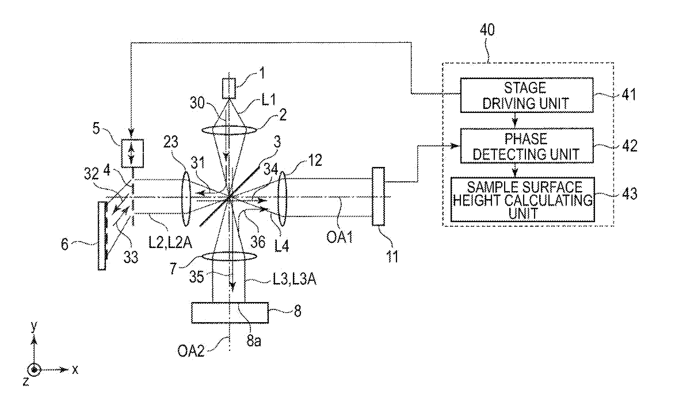
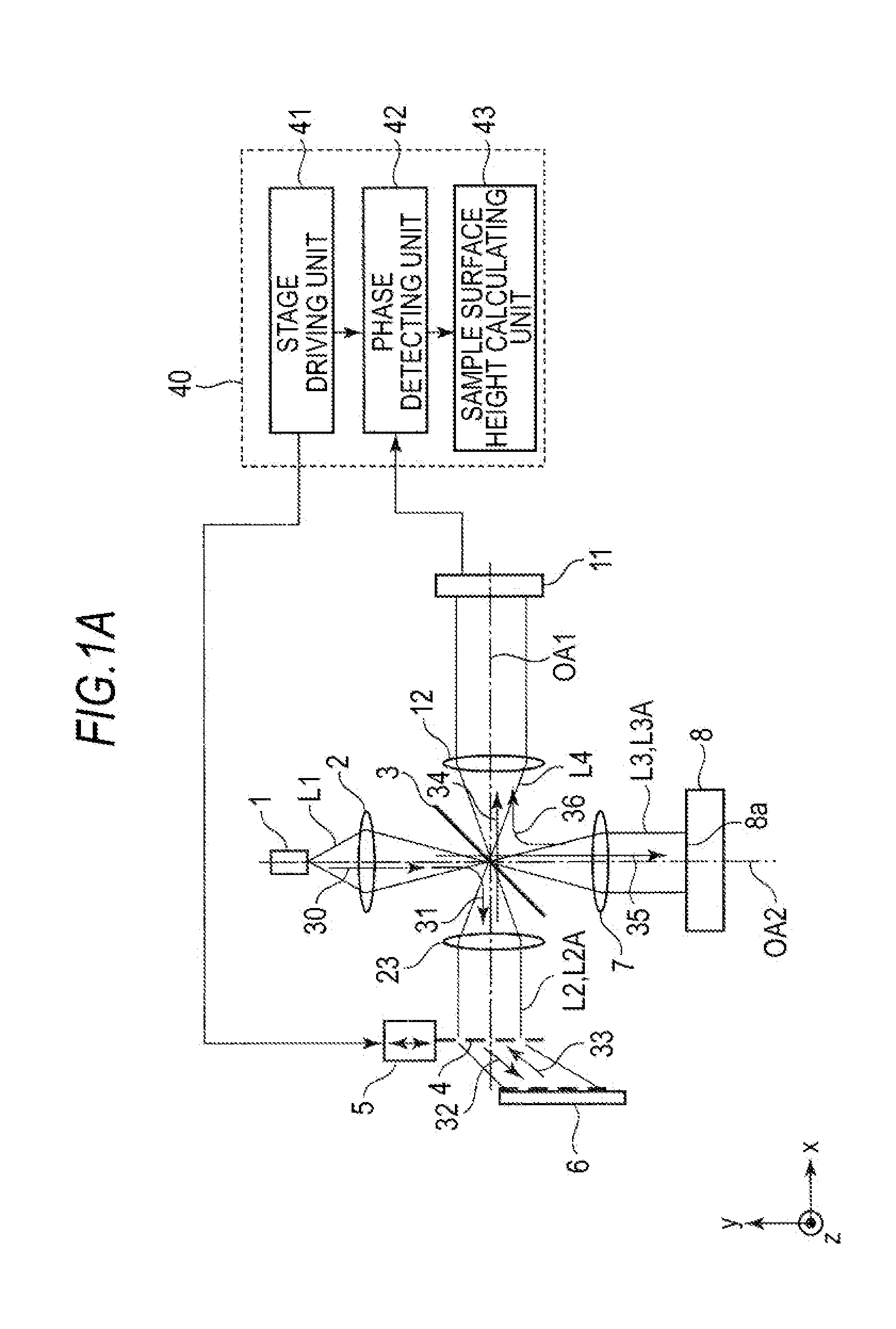
[0028]FIG. 1A is a diagram schematically illustrating a surface profile measuring apparatus according to a first embodiment.

[0029]The surface profile measuring apparatus according to the first embodiment includes a light source 1, a beam splitter 3, a first diffraction grating 4, a second diffraction grating 6, and a CCD 11.

[0030]The light source 1 emits a beam L1 having plural wavelengths.

[0031]The beam splitter 3 serves as an example of the splitter unit and splits the beam L1 which has been emitted into a reference beam L2 and a measuring beam L3.

[0032]The first diffraction grating 4 diffracts the reference beam L2 incident thereon.

[0033]The second diffraction grating 6 serves as an example of the reflection unit, and serves to reflect the reference beam L2 diffracted by the first diffraction grating 4 and to cause the reflected reference beam to be incident on the first diffraction grating 4 again. A reference beam L2A which has been incident on the first diffraction grating 4 a...

second embodiment

[0079]A surface profile measuring apparatus according to a second embodiment will be described below with reference to FIG. 8.

[0080]The second embodiment is different from the first embodiment, in that a cylindrical lens 22 and a lens 7a are disposed between the beam splitter 3 and the sample surface 8a, a CCD 11a is employed, and a third diffraction grating 9 and a cylindrical lens 10a are disposed between the lens 12 and the CCD 11a. Accordingly, in FIG. 8, the measurement of the sample surface 8a is limited to a linear shape to improve the resolution of measurement in the linear direction.

[0081]The constituents will foe described below.

[0082]The cylindrical lens 22 serves as an example of the first cylindrical lens and the cylinder axis thereof is parallel to the x axis direction. In the xy plane, the cylindrical lens 22 does not have a lens function, and a light flux 35 passing through, the cylindrical lens 22 is focused on the sample surface 8a by the lens 7a. In the yz plane, ...


PUM


Abstract

A surface profile measuring apparatus includes a reflection unit to reflect a reference beam diffracted by a first diffraction grating and cause the reflected reference beam to be incident on the first diffraction grating again, a detection unit to receive an interference beam in which the reference beam diffracted again by the first diffraction grating and a measuring beam reflected by a sample surface optically interfere with each other, and detect an interference intensity signal for each, wavelength in the interference beans, a shifting unit to shift the first diffraction grating in a direction perpendicular to a grating groove direction of the first diffraction grating, a calculation unit to calculates a phase on a basis of the interference intensity signal for each wavelength varying with a degree of shift, and a measurement unit to measure the sample surface.

Description

CROSS REFERENCE TO RELATED APPLICATIONS[0001]This application is entitled and claims the benefit of Japanese Patent Application No. 2012-098000, filed on Apr. 23, 2012, the disclosure of which including the specification, drawings and abstract is incorporated herein by reference in its entirety.BACKGROUND[0002]1. Technical Field[0003]The present technical field relates to a surface profile measuring apparatus and a surface profile measuring method using a phase-shifting method.[0004]2. Background Art[0005]A schematic diagram illustrating surface profile measurements using a phase-shifting method according to the related art is shown in FIG. 12.[0006]A beam from a light source 100 shown in FIG. 12 is split by a half mirror 101 and the split beams are applied to a sample surface 104 and a reference surface 102, respectively. Return beams from the sample surface 104 and the reference surface. 102 are superimposed through the half mirror 101. When the two return beams are superimposed, ...

Claims


Application Information

Patent Timeline
Patent Type & Authority Applications(United States)
IPC IPC(8): G01B11/24
CPCG01B11/2441G01B9/02015
Inventor FUKUI, ATSUSHIOIKAZE, HIROTOSHI
Owner PANASONIC INTELLECTUAL PROPERTY MANAGEMENT CO LTD
Why Eureka
Try Eureka