System and method for improving low-load efficiency of high power converters

a technology of high-power converters and low-load efficiency, which is applied in the direction of dc-dc conversion, efficient power electronics conversion, wind energy generation, etc., can solve the problems of significant drop in efficiency of power converters, and loss of efficiency at low loads

Inactive Publication Date: 2013-10-24
GENERAL ELECTRIC CO
View PDF3 Cites 29 Cited by
  • Summary
  • Abstract
  • Description
  • Claims
  • Application Information

AI Technical Summary

Benefits of technology

[0007]One exemplary aspect of the present disclosure is directed to a power converter system. The power converter system includes a power converter couplable (e.g. capable of being coupled to) to an input power source and configured to generate an output power substantially at a grid frequency. The power converter includes an inverter bridge circuit associated with an output phase of the power converter. The inverter br

Problems solved by technology

However, the efficiency of the power converters can drop significantly when the power converters are operated at low loads.
However, as the load condition drops to less than about 50% of rated output power for the power converter, the efficiency of the power converter drops significantly.
A primary reason for the efficiency loss at low loads can be due to the increased switching

Method used


Image

  • System and method for improving low-load efficiency of high power converters
  • System and method for improving low-load efficiency of high power converters
  • System and method for improving low-load efficiency of high power converters

Examples


Embodiment Construction

[0017]Reference now will be made in detail to embodiments of the invention, one or more examples of which are illustrated in the drawings. Each example is provided by way of explanation of the invention, not limitation of the invention. In fact, it will be apparent to those skilled in the art that various modifications and variations can be made in the present invention without departing from the scope or spirit of the invention. For instance, features illustrated or described as part of one embodiment can be used with another embodiment to yield a still further embodiment. Thus, it is intended that the present invention covers such modifications and variations as come within the scope of the appended claims and their equivalents.

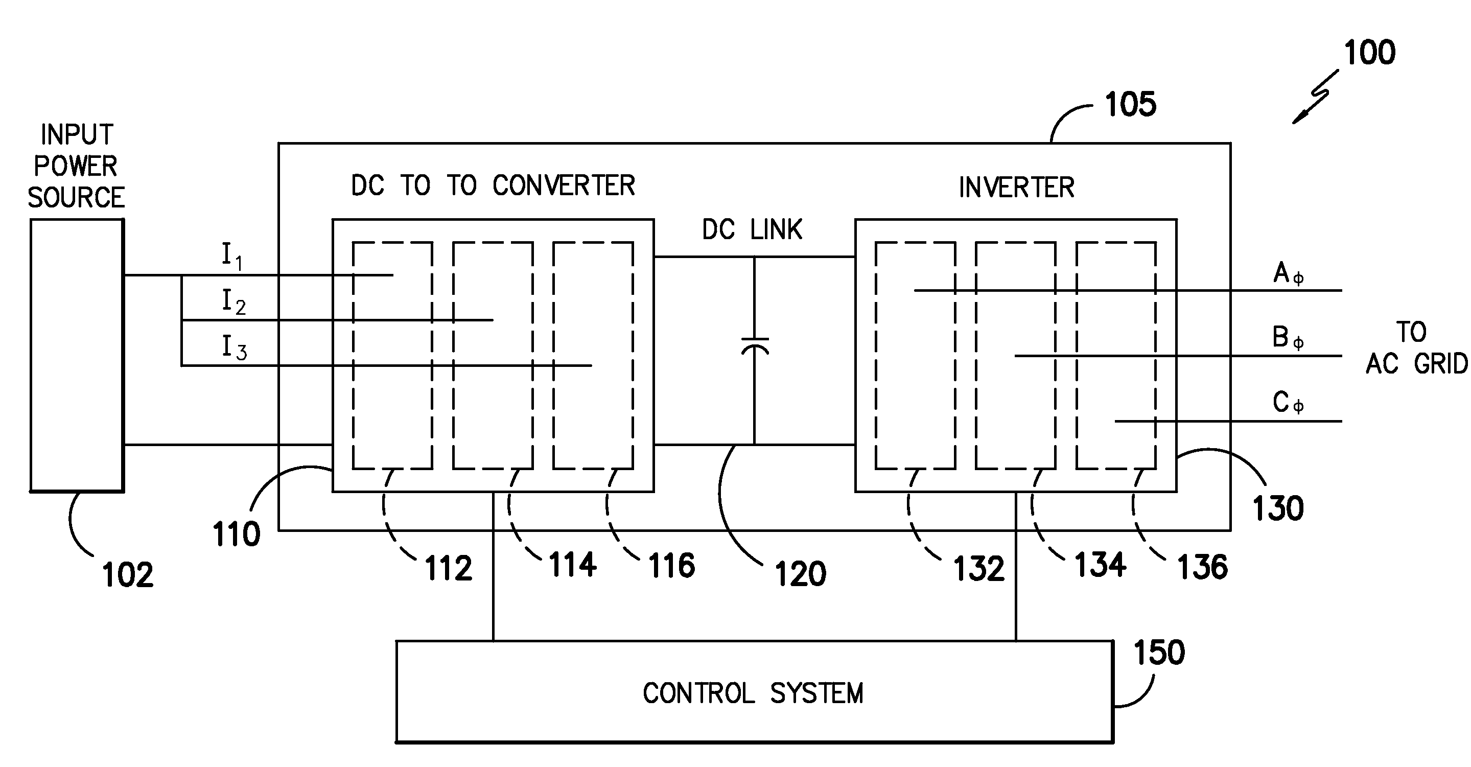
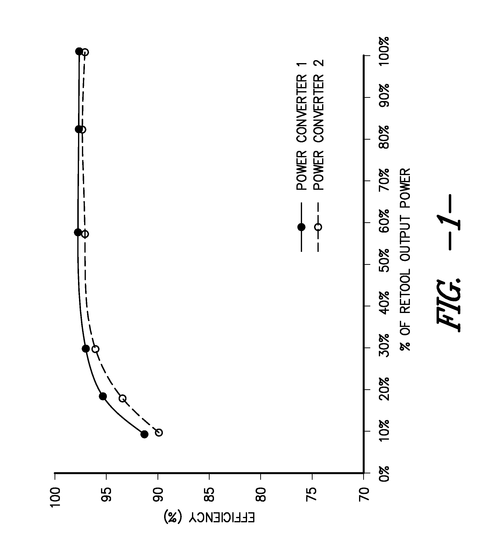
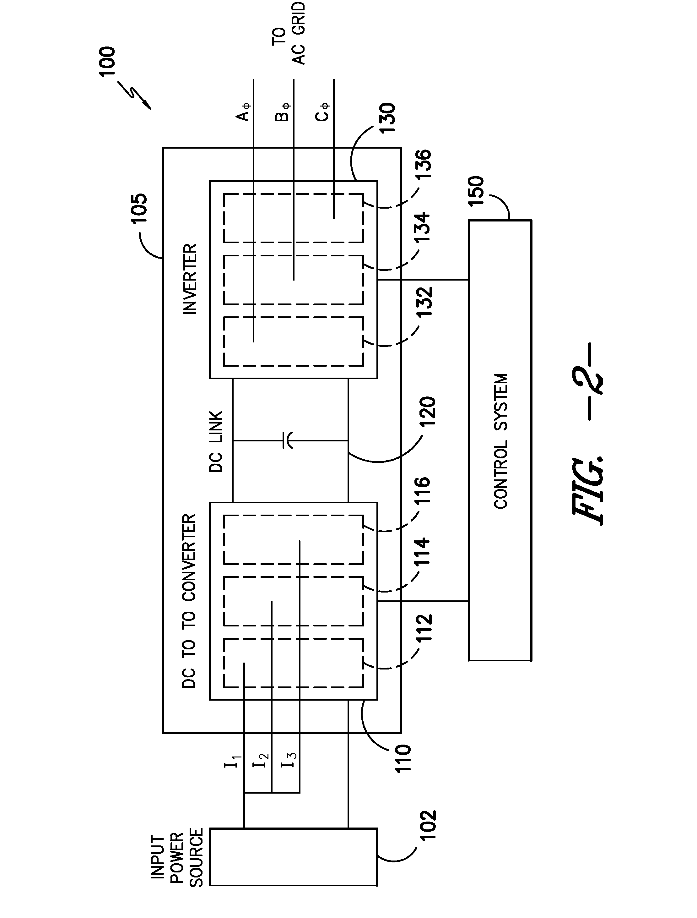
[0018]Generally, the present disclosure is directed to systems and methods for improving the efficiency of power converters used to convert energy generated by a renewable power source such as a photovoltaic array or a wind turbine, at reduced load conditio...


PUM


Abstract

Systems and methods for improving low-load efficiency of power converters are provided. The power converter can include one or more bridge circuits having multiple switching modules, such as insulated gate bipolar transistor (IGBT) modules, connected in parallel within the same bridge circuit. The power converter is configured to convert power from an input power source, such as a photovoltaic array or a wind turbine, into output power at a grid frequency. To avoid excessive switching losses at low load conditions, the power converter can be controlled to selectively operate a subset of the switching modules within the same bridge circuit based on a load condition for the power converter. The remaining switching modules in the bridge circuit can be disabled.

Description

FIELD OF THE INVENTION[0001]The present disclosure relates generally to renewable energy sources, and more particularly to a system and method for improving low-load efficiency of power converters used in renewable energy applications.BACKGROUND OF THE INVENTION[0002]Power converters are used in renewable energy applications to convert electrical power generated by a renewable energy source into power that is suitable for supply to an AC grid. For example, power converters can be used in wind energy applications to convert the alternating current generated by a wind turbine to a desired output frequency (e.g. 50 / 60 Hz) and voltage level. Power converters can be used in solar energy applications to convert the DC power generated by one or more photovoltaic arrays into suitable AC power for the AC grid.[0003]Power converters can be subject to stringent efficiency requirements at various voltages. The efficiency of the power converter can refer to a ratio of output power to input power...

Claims


Application Information

Patent Timeline
IPC IPC(8): H02M7/5387
CPCH02M3/1584H02M7/493Y02E10/56Y02E10/76H02M1/088Y02B70/10H02M1/0032H02M1/0054H02M1/0043
Inventor ZHU, HUIBINWAGONER, ROBERT GREGORYWILMER, DAVID SCOTT
Owner GENERAL ELECTRIC CO
Why Eureka
Try Eureka