Filter Test Strip

a filter and test strip technology, applied in the field of filter test strips, can solve the problems of inability to fully meet the use requirements, uneven surface of porous materials, gaps at the borders,

Active Publication Date: 2013-10-24
BIOPTIK TECH INC
View PDF4 Cites 1 Cited by
  • Summary
  • Abstract
  • Description
  • Claims
  • Application Information

AI Technical Summary

Benefits of technology

[0004]Therefore the primary object of the present invention is to provide a filt

Problems solved by technology

However, the porous material tends to form uneven surfaces and gaps at the borders.
It contains resi

Method used


Image

  • Filter Test Strip
  • Filter Test Strip
  • Filter Test Strip

Examples


Embodiment Construction

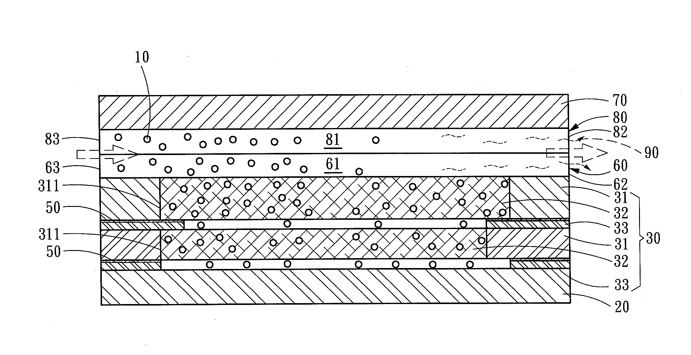
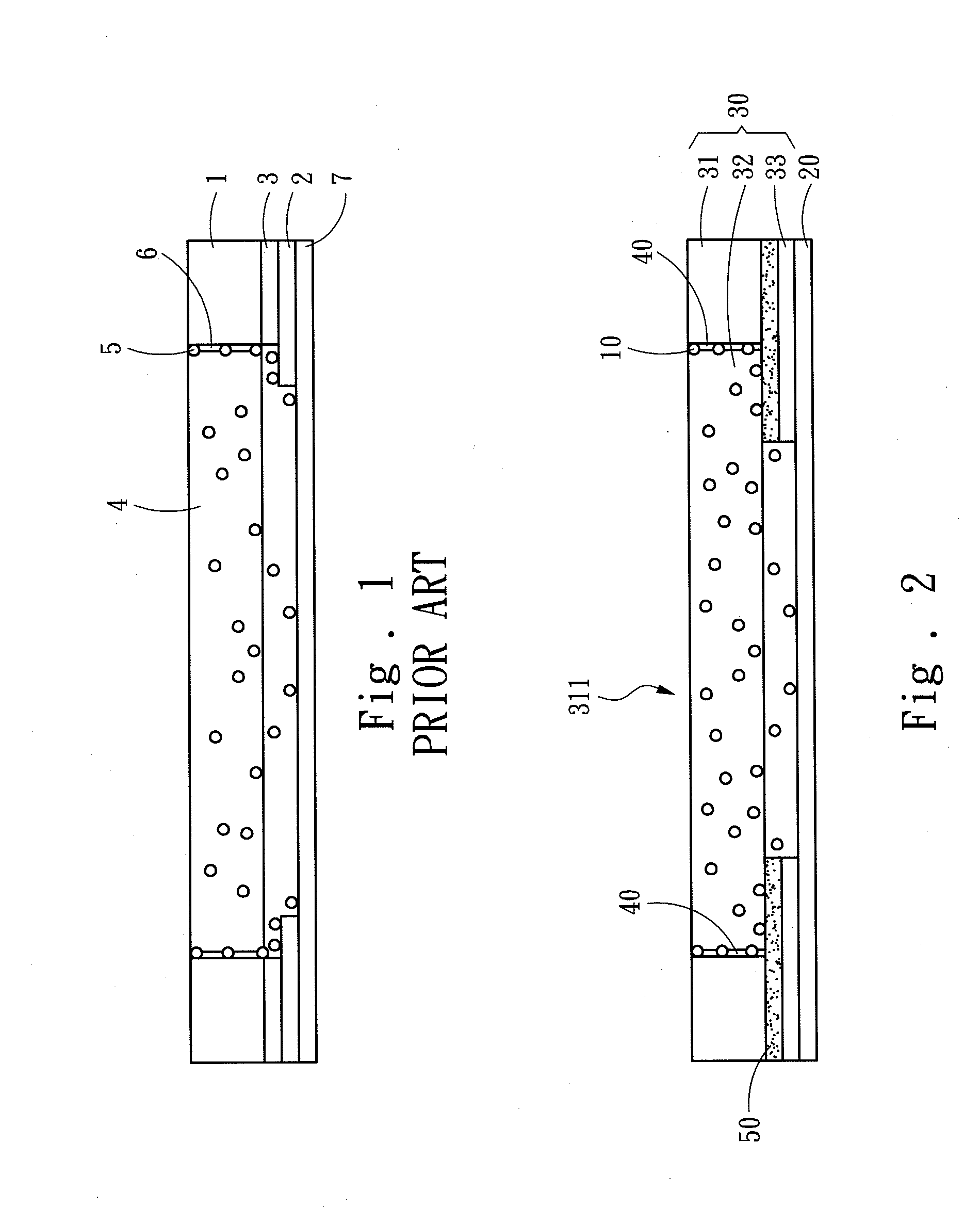
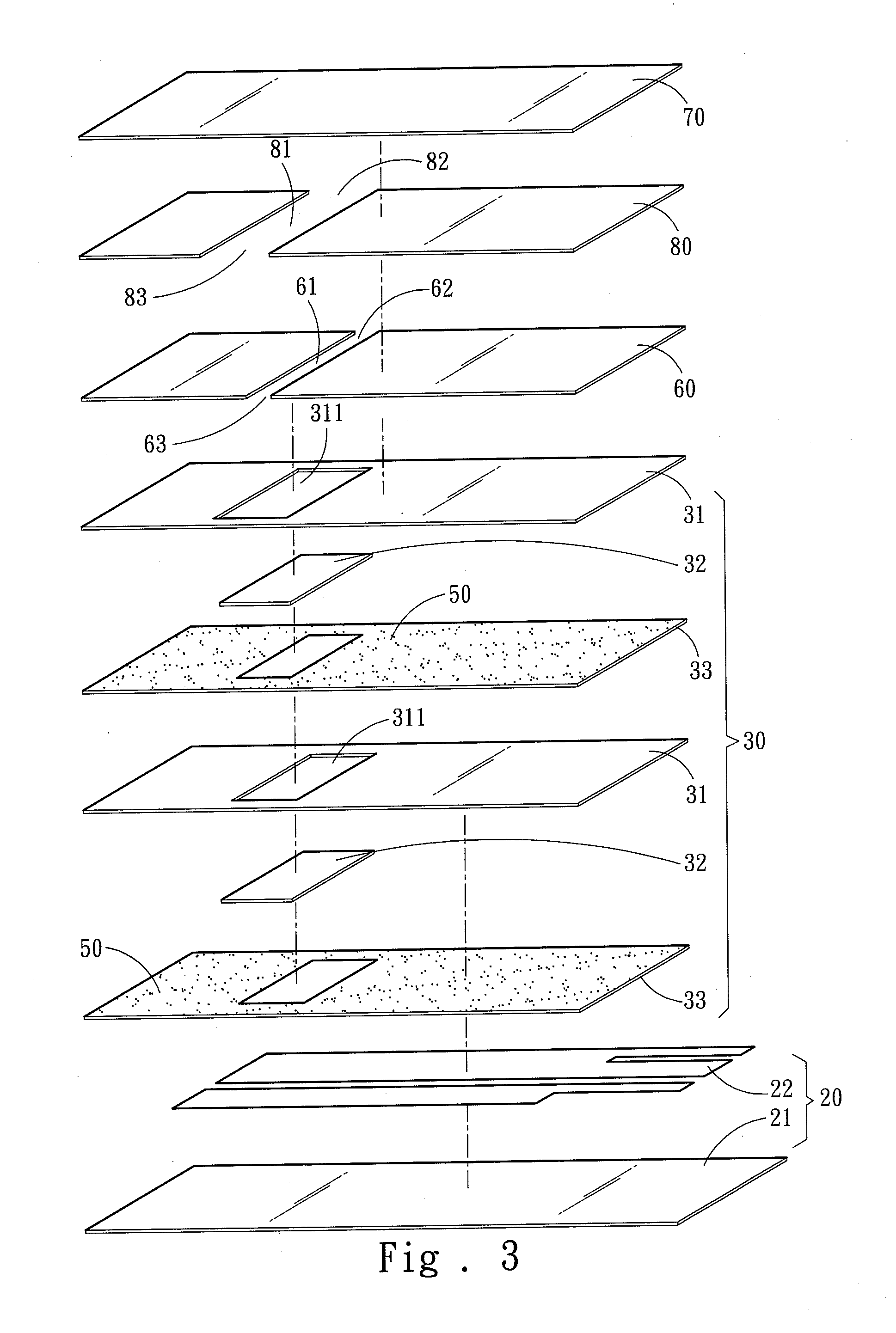
[0015]Please refer to FIG. 2, the present invention aims to provide a filter test strip to filter and test a specimen in liquid 10. It includes a test element 20 and a specimen filter assembly 30. The specimen filter assembly 30 is located on the test element 20, and includes at least one filter cotton holding layer 31, at least one filter cotton layer 32 and at least one cotton bonding layer 33. In the drawing each of the aforesaid layers is depicted by one set as an example for discussion. The filter cotton holding layer 31 has a filter channel 311 to allow the specimen in liquid 10 to pass through. The filter cotton layer 32 fills the corresponding filter channel 311. A gap 40 is formed between the filter cotton holding layer 31 and filter cotton layer 32. The gap 40 shown in the drawing is enlarged to facilitate discussion, and not the actual size. The cotton bonding layer 33 is located below the filter cotton holding layer 31 and bonded to the test element 20 via an adhesive 50...


PUM


Abstract

A filter test strip to filter and test a specimen in liquid includes a test element and a specimen filter assembly which is located on the test element and includes a filter cotton holding layer, a filter cotton layer and a cotton bonding layer.
The filter cotton holding layer has a filter channel to allow the specimen in liquid to pass through. The filter cotton layer fills the filter channel. A gap is formed between the filter cotton holding layer and filter cotton layer. The cotton bonding layer is located below the filter cotton holding layer and bonded to the test element via an adhesive which masks the gap. Hence the specimen in liquid can be prevented from seeping out through the gap with passing through the filter cotton layer. Therefore, the specimen in liquid can fully be filtered by the filter cotton layer to enhance test accuracy.

Description

FIELD OF THE INVENTION[0001]The present invention relates to a filter test strip and particularly to a filter structure for a filter test strip.BACKGROUND OF THE INVENTION[0002]Please refer to FIG. 1, a conventional filter test strip includes a filter cotton holding layer 1, a cotton bonding layer 2 and a test element 7. The filter cotton holding layer 1 and cotton bonding layer 2 are bonded by an adhesive 3 between them. The filter cotton holding layer 1 has a filter cotton 4 to filter blood 5 and remove blood cells to separate the blood cells and plasma, and allow only the plasma to pass through filter cotton to be captured. The plasma enters the test element 7 to be tested to get physiological data such as cholesterol, uric acid and the like.[0003]In the aforesaid conventional structure, the filter cotton 4 is made of porous material to filter the blood cells of the blood 5 and separate the blood cells and plasma. However, the porous material tends to form uneven surfaces and gap...

Claims


Application Information

Patent Timeline
IPC IPC(8): G01N1/34
CPCG01N1/34G01N33/525G01N33/558B01L2300/0681G01N2001/4088G01N2458/00G01N27/423B01L2300/0816B01L2300/0825G01N27/42B01L2300/0887G01N2015/0065
Inventor CHANG, YA-YUANLAI, CHIN-SHANYANG, CHIN-CHANGWU, KUN-LIEH
Owner BIOPTIK TECH INC
Why Eureka
Try Eureka