Apparatus and method for thermal assisted desorption ionization systems

a technology of ionization system and apparatus, which is applied in the direction of instruments, particle separator tube details, separation processes, etc., can solve the problems of inefficient transfer of heat to the sample by the carrier gas, and the time required to heat up the carrier gas to a sufficient temperature to enable the desorption of some analytes, so as to improve the resolution of the spectrometer, improve the transfer of ions, and improve the analysis of two or more samples

Active Publication Date: 2013-10-24
BRUKER SCI LLC
View PDF29 Cites 6 Cited by
  • Summary
  • Abstract
  • Description
  • Claims
  • Application Information

AI Technical Summary

Benefits of technology

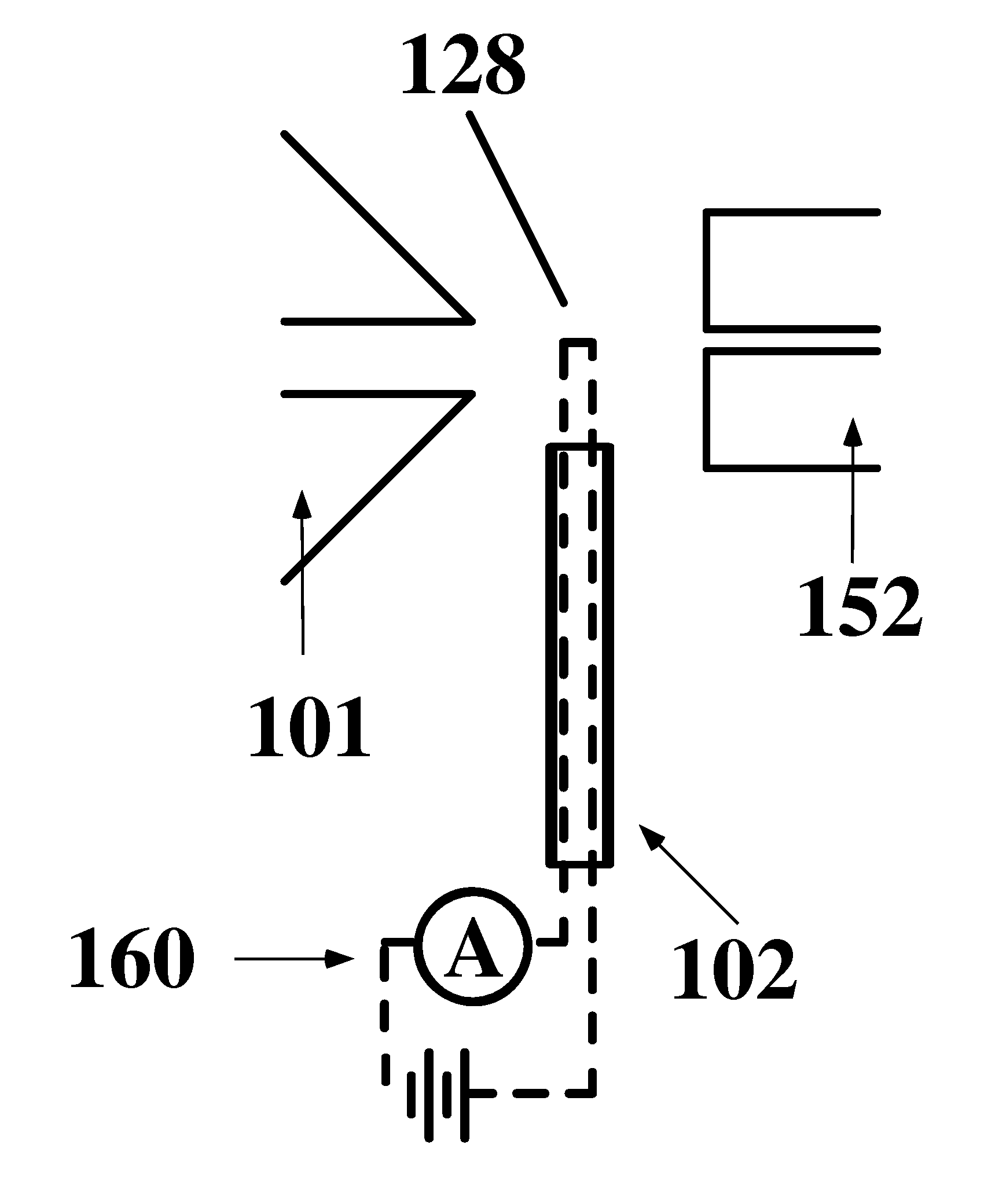
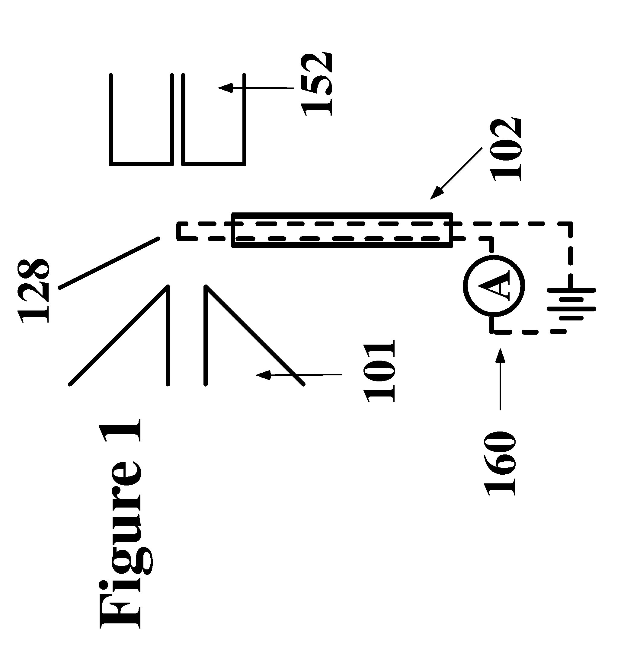
[0008]The kinetic energy of ions desorbed from or in close proximity to the wire mesh can be controlled by modulating the potential applied to the adjacent mesh or series of mesh. Control of the ion kinetic energy in the region between the sample laden wire mesh and the atmospheric pressure ionization (API)-inlet of a spectrometer can be used to improve the transfer of ions into the spectrometer for analysis of the one or more samples. Application of an electrical potential to the wire mesh enables limited control of the ion kinetic energy in the region between the sample laden wire mesh and the atmospheric pressure ionization (API)-inlet of a spectrometer which can have either a different electrical potential applied to its surface or be operated at the same potential as that wire mesh. Depending on the configuration of the spectrometer inlet the application of a potential can be used to improve resolution of the spectrometer. The ions that are formed near to the wire mesh can enter the spectrometer for analysis at atmospheric pressure or at a pressure that are higher than atmospheric when electrical potentials are able to draw or push those ions into the volume of the spectrometer.
[0010]In traditional IMS devices ionization of neutral molecules occurs in the volume of the spectrometer. Ions are generated using radioactive particle emission from elements such as 3H (tritium), 63Ni, or other radioactive materials. Plasma-based ionization is also feasible using electrical discharge in the volume of the sampling region in order to produce ions which subsequently interact with the neutral molecules to ionize them in that volume. The production of ions inside of the volume of the IMS reduces the range of ion kinetic energies for the ionized particles since the electrical field is uniform in that region of ionization.
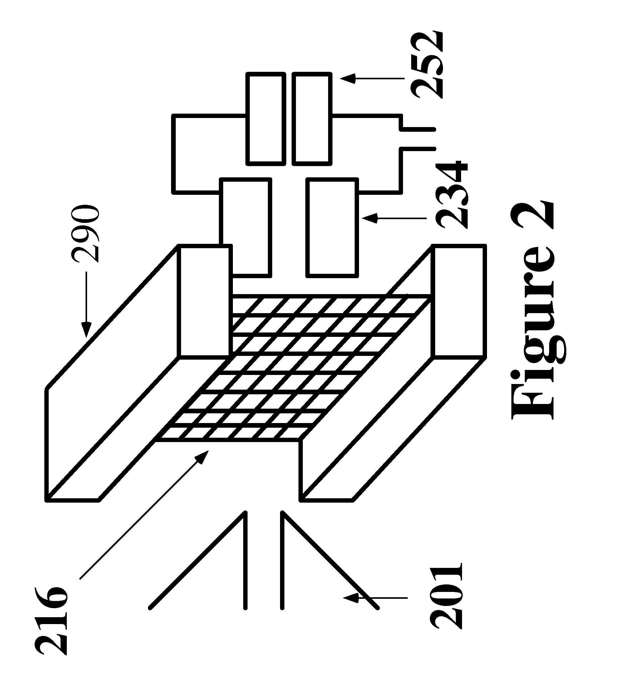
[0011]The position of the ionization source relative to the IMS determines a distance over which ions trajectory must follow before entering the IMS. Positioning of the IMS ionization region even a very short distance away from the entrance to the spectroscopy system results in a decline in achievable resolution of the spectroscopy system. In the case of ambient pressure ionization from a heated wire mesh, rapid vaporization of the sample into the carrier gas from the sample laden wire mesh can occur in close proximity to the entrance of the IMS between the carrier gas source, and the inlet of the IMS spectroscopy system. Thus the position of the sample laden wire mesh relative to the entrance of the IMS spectrometer influences the kinetic energy of the ions formed from those desorbed molecules. The kinetic energy distribution of ions that are formed immediately in the vicinity of the wire mesh in close proximity to the IMS can be corrected. As the majority of ions produced in the experiment are produced at or near atmospheric pressure in close proximity to the wire mesh those ions may be formed inside the volume of the ion mobility spectrometer (IMS). The kinetic energy of ions is related to the electrical fields in which they are formed. In the caser of the IMS systems the kinetic energy is thought to be uniform when all ions are formed inside the tube, however in order to effect sampling of ions for spectroscopic analysis a potential is applied to wires that form a Bradbury-Nielson gate a short distance away from the he ionizing region. The distance between the BN-gate and the position where the ions are formed effects their kinetic energy. The ability to change the energy of the ions formed in very close proximity to the IMS entrance improves the control of those ions afforded by the ion focusing of the IMS. Application of a electrical potential to the wire mesh in close proximity to the ionization region therefore will change the ion kinetic energy of those ions that are closer to the wire mesh to a greater degree than those that have been formed further away from the wire mesh. Linking the application of electrical potential applied to the wire mesh with the electrical potential used to open and close the BN-gate enables those ions that are further from the gate to catch up to the ions that are closer thus generating a collection of ions that have a more uniform kinetic energy as they are transferred from the ionization region into the ion separation region of the spectrometer.
[0013]In an alternative embodiment of the invention application of a small potential to the kinetic energy controlling mesh will result in rejection of the ions by the spectrometer. The action of rejection ions whose kinetic energy is different than those ions formed inside the atmospheric pressure region of the spectrometer can be used to further improve the resolution of the spectrometer as it reduces the kinetic energy of the ions being sampled.
[0015]In an alternative embodiment of the invention a sample can be deposited onto a second surface that can be placed in close proximity to the mesh through which the ionizing carrier gas can flow. Sample related molecules can be desorbed from the second surface as a result of the current applied to the mesh. Sample related molecules can be desorbed from the second surface as a result of heating of the mesh by increasing the current running through the mesh. In various embodiments of the invention, by increasing the current passed through the wire, increased radiant heating can be generated. In various embodiments of the invention, increased radiant heat can effect desorption of less volatile components in a sample.

Problems solved by technology

Unfortunately, the heating of the carrier gas to a sufficient temperature to enable desorption of some analytes takes considerable time.
Further, the transfer of heat to the sample by that gas is not very efficient.

Method used


Image

  • Apparatus and method for thermal assisted desorption ionization systems
  • Apparatus and method for thermal assisted desorption ionization systems
  • Apparatus and method for thermal assisted desorption ionization systems

Examples


Embodiment Construction

Definitions

[0040]The transitional term “comprising” is synonymous with “including,”“containing,” or “characterized by,” is inclusive or open-ended and does not exclude additional, unrecited elements or method steps.

[0041]The transitional phrase “consisting of” excludes any element, step, or ingredient not specified in the claim, but does not exclude additional components or steps that are unrelated to the invention such as impurities ordinarily associated with a composition.

[0042]The transitional phrase “consisting essentially of” limits the scope of a claim to the specified materials or steps and those that do not materially affect the basic and novel characteristic(s) of the claimed invention.

[0043]A vacuum of atmospheric pressure is 1 atmosphere=760 torr. Generally, ‘approximately’ in this pressure range encompasses a range of pressures from below 101 atmosphere=7.6×10³ torr to 10−1 atmosphere=7.6×101 torr. A vacuum of below 10−3 torr would constitute a high vacuum. Generally, ‘a...


PUM


Abstract

The present invention is directed to a method and device to desorb an analyte using heat to allow desorption of the analyte molecules, where the desorbed analyte molecules are ionized with ambient temperature ionizing species. In various embodiments of the invention a current is passed through a mesh upon which the analyte molecules are present. The current heats the mesh and results in desorption of the analyte molecules which then interact with gas phase metastable neutral molecules or atoms to form analyte ions characteristic of the analyte molecules.

Description

PRIORITY CLAIM[0001]This application is a continuation of (1) U.S. patent application Ser. No. 13 / 364,322 entitled “APPARATUS AND METHOD FOR THERMAL ASSISTED DESORPTION IONIZATION SYSTEMS”, inventors: Jordan Krechmer and Brian D. Musselman, filed Feb. 2, 2012 which claims priority to (2) U.S. Provisional Patent Application No. 61 / 439,866 entitled “APPARATUS FOR THERMAL ASSISTED DESORPTION IONIZATION”, inventors Jordan Krechmer and Brian D. Musselman, filed Feb. 5, 2011; (3) U.S. Provisional Patent Application No. 61 / 582,204 and entitled “APPARATUS AND METHOD FOR THERMAL ASSISTED DESORPTION IONIZATION SYSTEMS” by, inventors Jordan Krechmer and Brian D. Musselman, filed Dec. 30, 2011, the contents of each of which are incorporated herein by reference in their entireties, and (4) U.S. Provisional Patent Application No. 61 / 587,218 and entitled “APPARATUS AND METHOD FOR THERMAL ASSISTED DESORPTION IONIZATION SYSTEMS”, inventors Jordan Krechmer and Brian D. Musselman, filed Jan. 17, 2012,...

Claims


Application Information

Patent Timeline
Patent Type & Authority Applications(United States)
IPC IPC(8): H01J49/04
CPCH01J49/04H01J49/14Y10T436/24H01J49/049H01J49/26G01N27/64H01J49/004H01J27/26H01J49/126G01N27/626H01J49/0431H01J49/10H01J49/24
Inventor KRECHMER, JORDANMUSSELMAN, BRIAN D.
Owner BRUKER SCI LLC
Why Eureka
Try Eureka