Method for determining crankcase breach and oil level

a technology of oil level and crankcase, applied in the direction of liquid/fluent solid measurement, machines/engines, instruments, etc., can solve the problems of cap off, dipstick out of position, and disconnected fresh air hose (breather tube) and other problems, to achieve the effect of reducing the degradation of various engine components

Active Publication Date: 2013-10-24
FORD GLOBAL TECH LLC
View PDF18 Cites 28 Cited by
  • Summary
  • Abstract
  • Description
  • Claims
  • Application Information

AI Technical Summary

Benefits of technology

[0002]Engines may include crankcase ventilation systems to vent gases out of the crankcase and into an engine intake manifold to provide evacuation of gases from inside the crankcase in order to reduce degradation of various engine components in the crankcase.
[0006]However, the inventors herein have recognized that such approaches may add additional hardware to such monitoring systems, e.g., additional sensors and valves, thus increasing costs and complexity of a crankcase ventilation monitoring system. Additionally, some of these sensors may be underutilized, e.g., the crankcase pressure sensor may only be used for crankcase breach detection, thus limiting the value of such sensors.
[0009]Thus, in one example, a common crankcase sensor may be used both for detecting crankcase breach and for sensing oil level. In doing so, engine hardware may be reduced, lowering cost and reducing system complexity. Further, by immersing the pressure sensor in engine oil, mechanical damping may be provided by the oil, reducing noise in the pressure signal and improving accuracy of the pressure detection.

Problems solved by technology

For example, a fresh air hose (breather tube) may become disconnected, an oil cap may be off or loose, a dipstick may be out of position, and / or other seals in the crankcase ventilation system may be broken.
Following a crankcase breach, degradation of various components included in the crankcase may occur, or the gases may not be properly ingested into the engine to be rendered innocuous.
However, the inventors herein have recognized that such approaches may add additional hardware to such monitoring systems, e.g., additional sensors and valves, thus increasing costs and complexity of a crankcase ventilation monitoring system.
Additionally, some of these sensors may be underutilized, e.g., the crankcase pressure sensor may only be used for crankcase breach detection, thus limiting the value of such sensors.

Method used


Image

  • Method for determining crankcase breach and oil level
  • Method for determining crankcase breach and oil level
  • Method for determining crankcase breach and oil level

Examples


Embodiment Construction

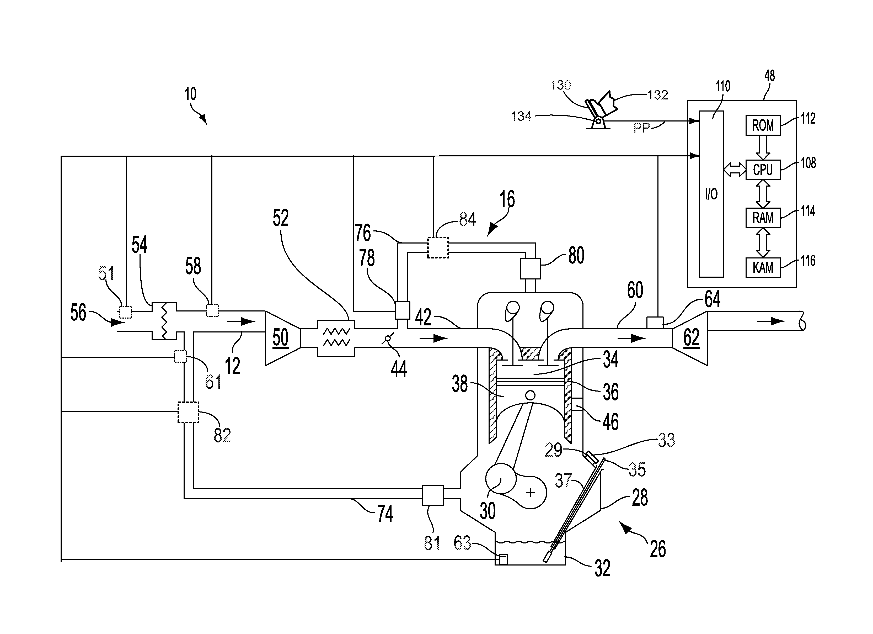
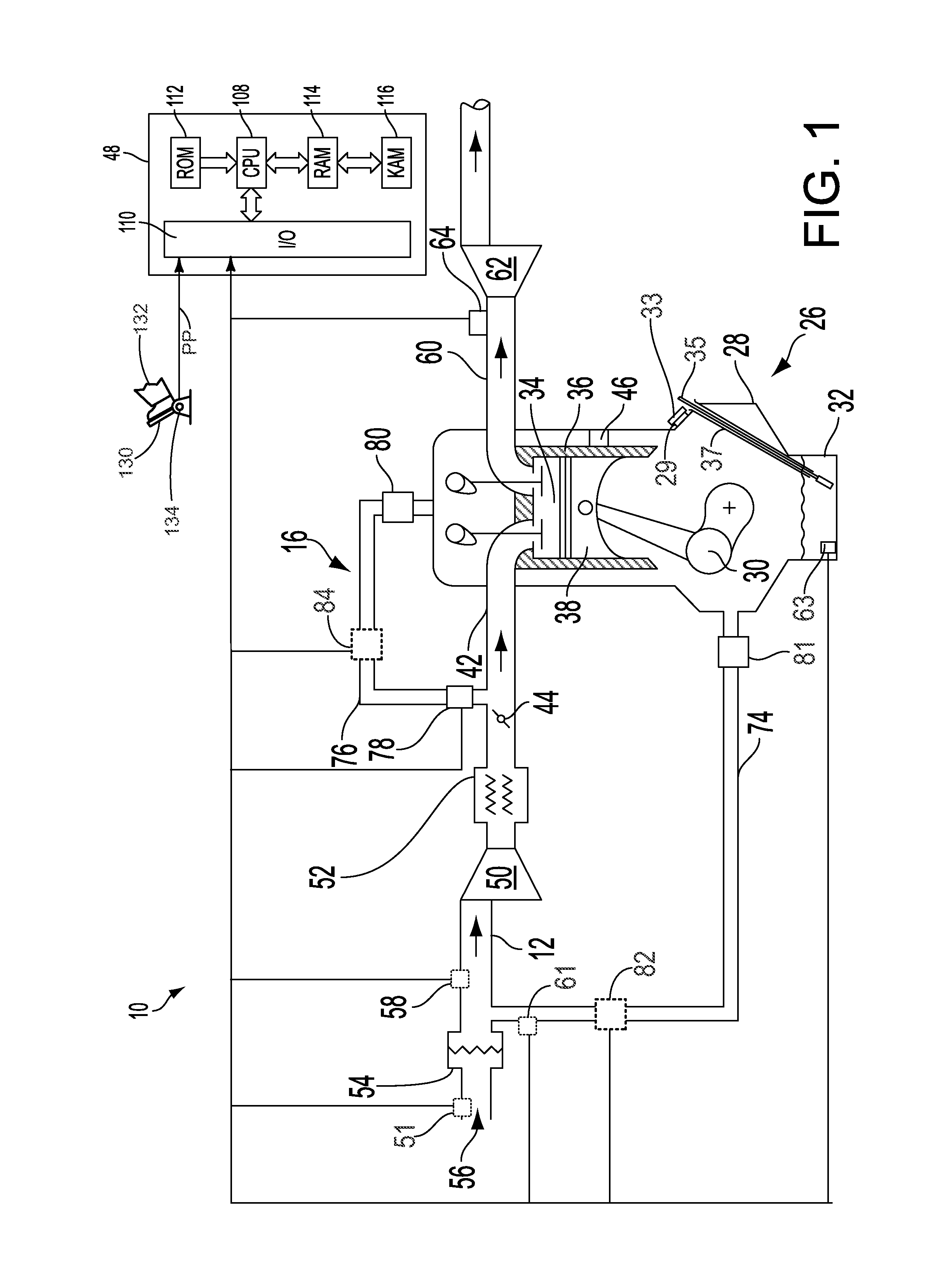
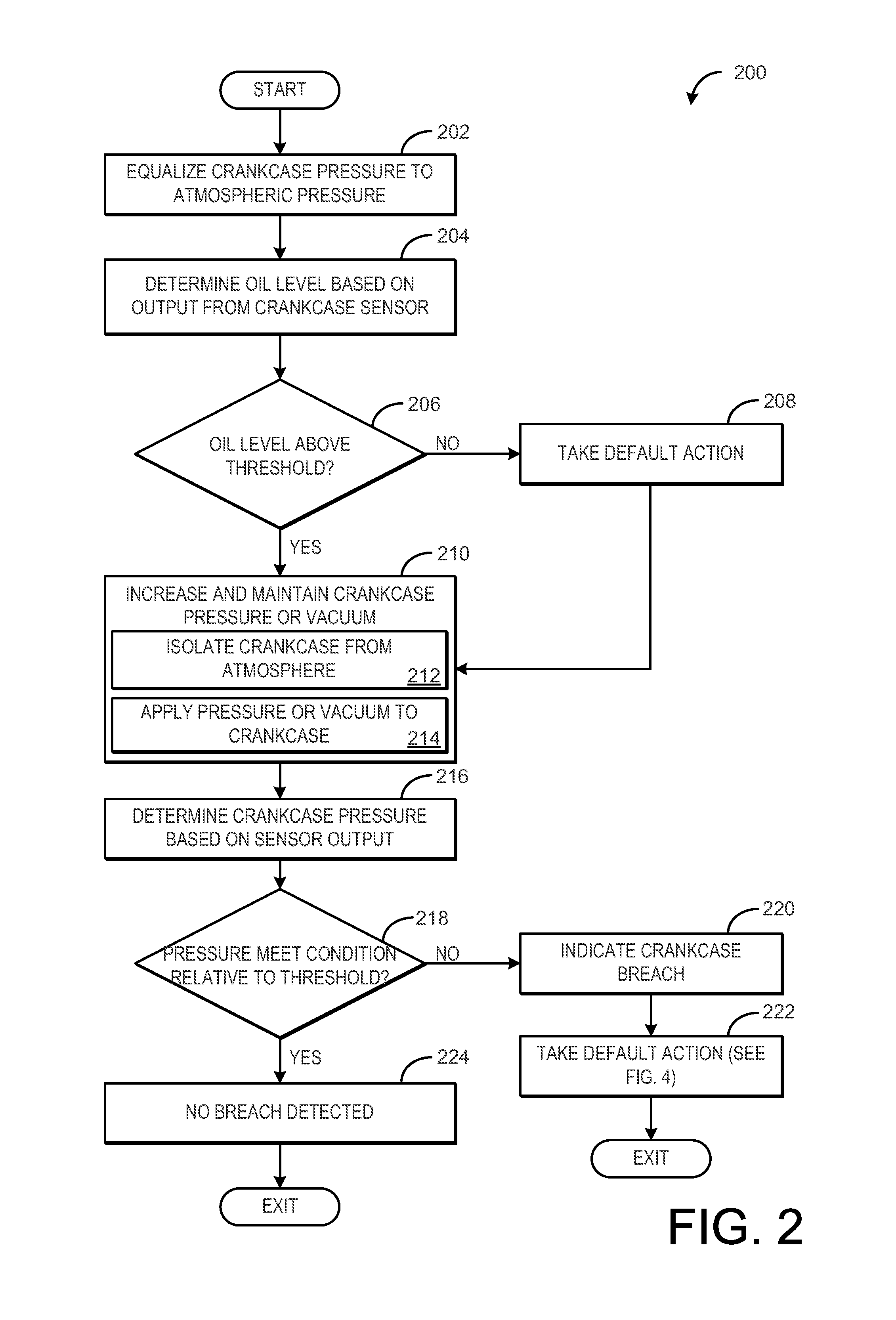
[0016]In order to detect and respond to crankcase breach, where crankcase gas vapors may escape to the atmosphere via an uncapped lubricant filling port or unseated dipstick, for example, engine crankcases may include a sensor, such as a pressure sensor. Under certain operating conditions when the crankcase is isolated from the atmosphere and pressure or vacuum is applied to the crankcase, the sensor may be used to detect breach. In addition, if the crankcase sensor is immersed in the oil in the oil sump, when the crankcase pressure is equalized with atmospheric pressure or another reference pressure, the crankcase sensor may be also be used as an oil level sensor. Thus, a single sensor may be utilized to both detect breach and determine oil level. FIG. 1 is a diagram of engine including a crankcase sensor immersed in engine oil. The engine of FIG. 1 also includes a controller which may carry out one or more control routines, such as the methods of FIG. 2 and FIG. 4. Example pressur...


PUM


Abstract

Embodiments for detecting crankcase breach are provided. In one example, a method includes indicating both crankcase ventilation system degradation and a crankcase oil sump level based on a common crankcase sensor. In this way, the same sensor can provide both crankcase breach detection and oil level determination.

Description

FIELD[0001]The present disclosure relates to crankcase breach detection.BACKGROUND AND SUMMARY[0002]Engines may include crankcase ventilation systems to vent gases out of the crankcase and into an engine intake manifold to provide evacuation of gases from inside the crankcase in order to reduce degradation of various engine components in the crankcase.[0003]Under certain conditions, crankcase ventilation systems may be monitored to identify breaches in the system. For example, a fresh air hose (breather tube) may become disconnected, an oil cap may be off or loose, a dipstick may be out of position, and / or other seals in the crankcase ventilation system may be broken. Following a crankcase breach, degradation of various components included in the crankcase may occur, or the gases may not be properly ingested into the engine to be rendered innocuous.[0004]Various approaches may be used to monitor crankcase ventilation system integrity. For example, a pressure sensor may be used in th...

Claims


Application Information

Patent Timeline
Patent Type & Authority Applications(United States)
IPC IPC(8): F02D28/00
CPCG01M15/06F02B77/08F01M1/18F01M11/0004F01M11/12G01F23/804
Inventor PURSIFULL, ROSS DYKSTRA
Owner FORD GLOBAL TECH LLC
Why Eureka
Try Eureka