Submerged combustion melter comprising a melt exit structure designed to minimize impact of mechanical energy, and methods of making molten glass

Active Publication Date: 2013-10-31
JOHNS MANVILLE CORP
View PDF37 Cites 83 Cited by
  • Summary
  • Abstract
  • Description
  • Claims
  • Application Information

AI Technical Summary

Benefits of technology

[0019]d) cooling the fluid-cooled transition channel sufficiently to form a frozen glass layer or highly viscous glass layer, or combination thereof, on inner surfaces

Problems solved by technology

Using submerged combustion burners produces violent turbulence of the molten glass and results in a high degree of mechanical energy in the submerged combustion melter that, without modification, is undesirably transferred to the conditioning channel.
Given that long life is a goal for submerged combustion melters and conditioning channels attached thereto, this transference of mechanical energy from the melter to the conditioning cha

Method used


Image

  • Submerged combustion melter comprising a melt exit structure designed to minimize impact of mechanical energy, and methods of making molten glass
  • Submerged combustion melter comprising a melt exit structure designed to minimize impact of mechanical energy, and methods of making molten glass
  • Submerged combustion melter comprising a melt exit structure designed to minimize impact of mechanical energy, and methods of making molten glass

Examples


embodiment 1

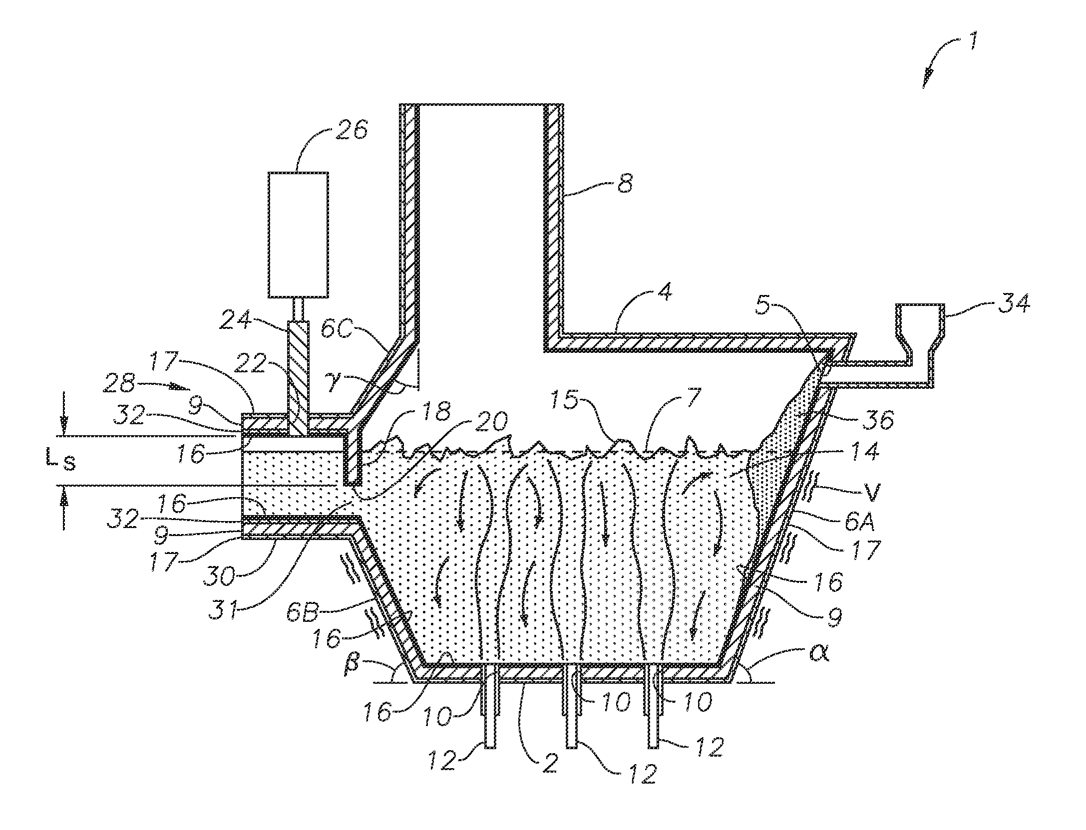
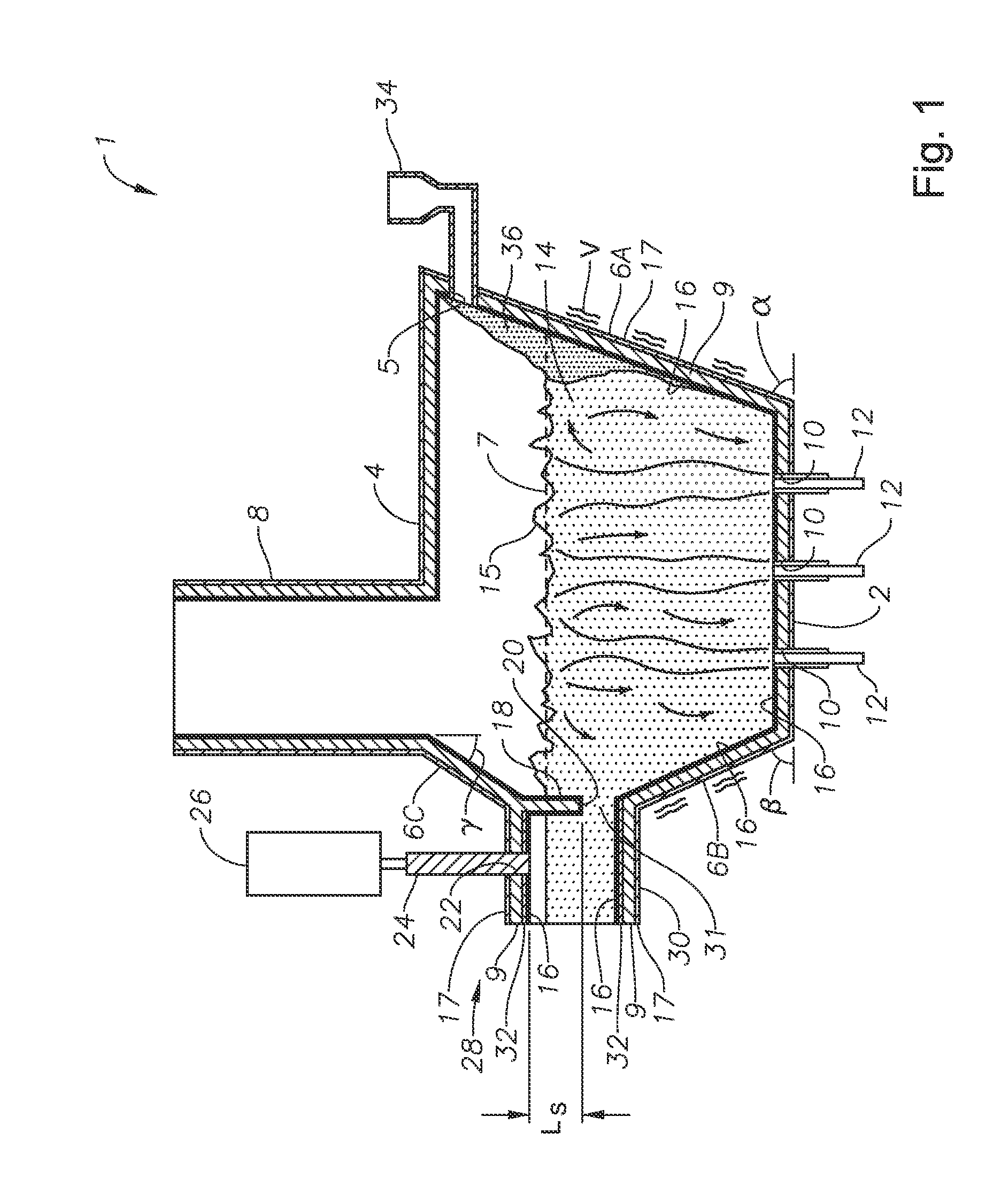
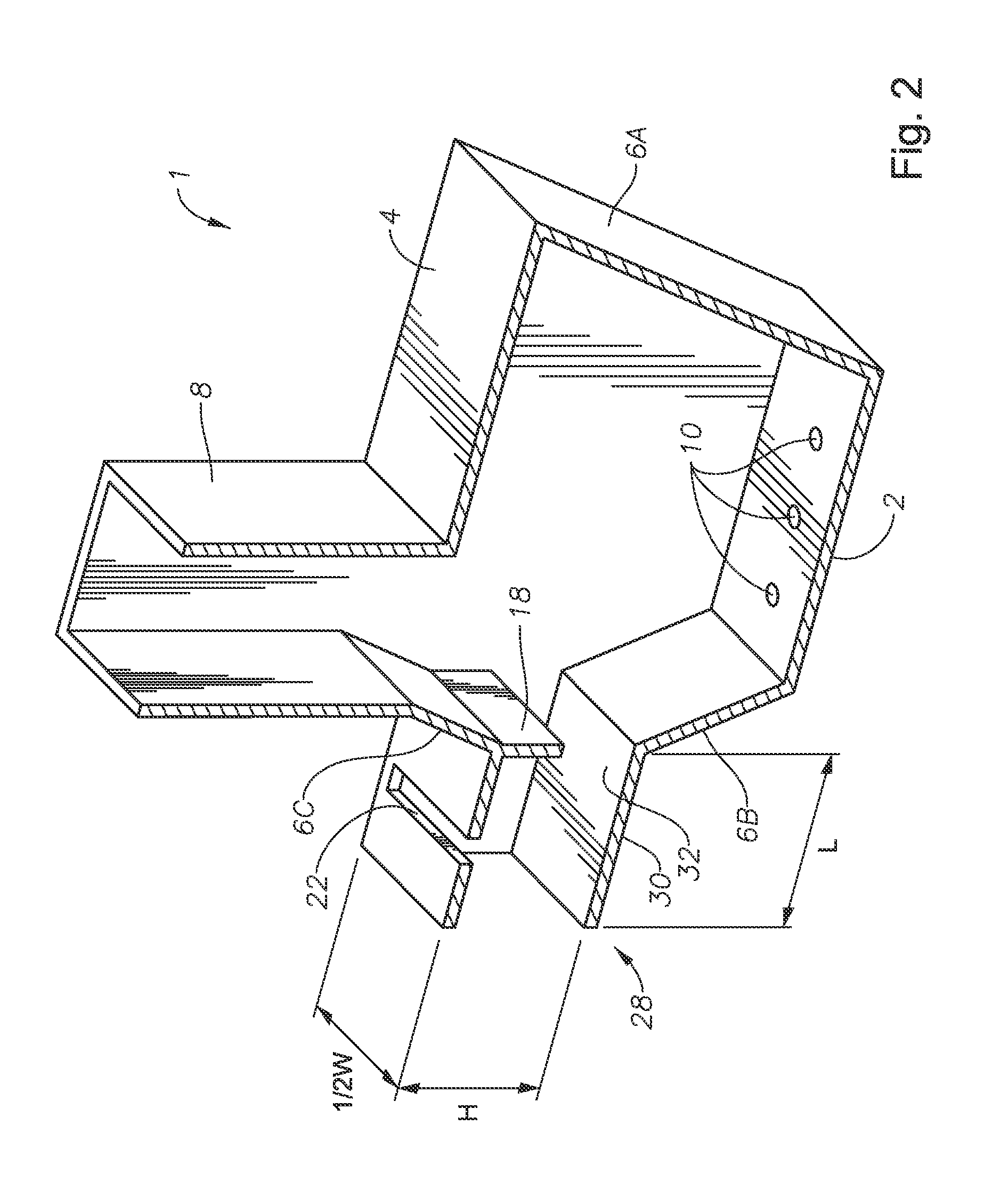
[0037]Referring now to the figures,FIGS. 1, 3, and 5, are vertical sectional views, of three melter apparatus embodiments in accordance with the present disclosure, while FIGS. 2, 4, and 6 are perspective views of the sectional views of the melter embodiments illustrated in FIGS. 1, 3, and 5, respectively. The same numerals and symbols are used for the same or similar features in the various figures. In the perspective views illustrated in FIGS. 2, 4, and 6, it will be understood in each case that some components are not illustrated in order to illustrate more clearly the key features of each embodiment. Melter apparatus embodiment 1 of FIGS. 1 and 2 comprises a floor 2, a roof or ceiling 4, a feed end wall 6A, a first portion of an exit end wall 6B, and a second portion of the exit end wall 6C. Each of floor 2, roof 4, and walls 6A, 6B, and 6C comprise a metal shell 17 and a refractory panel 9, some or all of which may be fluid-cooled. Feed end wall 6A and exit end wall portion 6B ...

embodiment 100

[0050]FIGS. 8, 9 and 10 are logic diagrams illustrating three methods in accordance with the present disclosure. Embodiment 100 of FIG. 8 includes the steps of feeding at least one partially vitrifiable material into a feed inlet of a melting zone of a melter vessel comprising a floor, a ceiling, and a wall connecting the floor and ceiling at a perimeter of the floor and ceiling, the melter vessel comprising a batch feeder attached to the wall or ceiling and an exit end comprising a melter exit structure for discharging molten glass, the melter exit structure fluidly and mechanically connecting the melter vessel to a molten glass conditioning channel, box 102. The method further includes heating the at least one partially vitrifiable material with at least one burner directing combustion products into the melting zone under a level of the molten glass in the zone, and forming the turbulent molten glass while imparting mechanical energy to the melter vessel, box 104. The method also ...

embodiment 200

[0051]FIG. 9 is a logic diagram of another method embodiment 200, which includes the steps of feeding at least one partially vitrifiable material into a feed inlet of a melting zone of a melter vessel comprising a floor, a ceiling, and a wall connecting the floor and ceiling at a perimeter of the floor and ceiling, the melter vessel comprising a batch feeder attached to the wall or ceiling and an exit end comprising a melter exit structure for discharging molten glass, the melter exit structure fluidly and mechanically connecting the melter vessel to a molten glass conditioning channel, box 202, and heating the at least one partially vitrifiable material with at least one burner directing combustion products into the melting zone under a level of the molten glass in the zone, and forming the turbulent molten glass while imparting mechanical energy to the melter vessel, box 204. The method also includes discharging molten glass from the melter vessel through a fluid-cooled transition...


PUM

PropertyMeasurementUnit
Lengthaaaaaaaaaa
Lengthaaaaaaaaaa
Lengthaaaaaaaaaa

Abstract

A melter apparatus includes a floor, a ceiling, and a wall connecting the floor and ceiling at a perimeter of the floor and ceiling, a melting zone being defined by the floor, ceiling and wall, the melting zone having a feed inlet and a molten glass outlet positioned at opposing ends of the melting zone. Melter apparatus include an exit end having a melter exit structure for discharging turbulent molten glass formed by one or more submerged combustion burners, the melter exit structure fluidly and mechanically connecting the melter vessel to a molten glass conditioning channel. The melter exit structure includes a fluid-cooled transition channel configured to form a frozen glass layer or highly viscous glass layer, or combination thereof, on inner surfaces of the fluid-cooled transition channel and thus protect the melter exit structure from mechanical energy imparted from the melter vessel to the melter exit structure.

Description

BACKGROUND INFORMATION[0001]1. Technical Field[0002]The present disclosure relates generally to the field of combustion furnaces and methods of use, and more specifically to improved submerged combustion melters and methods of use in producing molten glass.[0003]2. Background Art[0004]In submerged combustion glass melting, combustion gases are injected beneath the surface of the molten glass and rise upward through the melt. The glass is heated at a high efficiency via the intimate contact with the combustion gases. The melter exit may be connected to a conditioning channel. Using submerged combustion burners produces violent turbulence of the molten glass and results in a high degree of mechanical energy in the submerged combustion melter that, without modification, is undesirably transferred to the conditioning channel. Given that long life is a goal for submerged combustion melters and conditioning channels attached thereto, this transference of mechanical energy from the melter ...

Claims


Application Information

Patent Timeline
IPC IPC(8): C03B5/26C03B5/23
CPCC03B3/00C03B3/023C03B5/04C03B5/167C03B5/20C03B5/2356C03B5/26C03B5/44C03B2211/22C03B2211/70Y02P40/50
Inventor MOBLEY, JOHN EUFORDHUBER, AARON MORGANENRIGHT, RYAN PATRICK
Owner JOHNS MANVILLE CORP
Why Eureka
Try Eureka