High temperature electrostatic chuck with real-time heat zone regulating capability

a technology of electrostatic chuck and real-time heat zone, which is applied in the direction of electrostatic holding device, basic electric element, electric apparatus, etc., can solve the problems of metal contamination under processing chemistry, the operating temperature of the clamping device and the organic o-ring cannot function properly, and the performance limit of the high-temperature organic o-ring exceeds the performance limi

Active Publication Date: 2013-10-31
APPLIED MATERIALS INC
View PDF13 Cites 167 Cited by
  • Summary
  • Abstract
  • Description
  • Claims
  • Application Information

AI Technical Summary

Problems solved by technology

However, the metal clamping devices and organic O-rings cannot function properly at elevated temperatures, such as at a temperature higher than 350° C. At 350° C., the operating temperature exceeds the performance limits for high temperature organic O-Rings.
Additionally, metal clamping devices, generally made from refractory metal such as titanium, will also introduce metal contamination under processing chemistry.

Method used


Image

  • High temperature electrostatic chuck with real-time heat zone regulating capability
  • High temperature electrostatic chuck with real-time heat zone regulating capability
  • High temperature electrostatic chuck with real-time heat zone regulating capability

Examples


Embodiment Construction

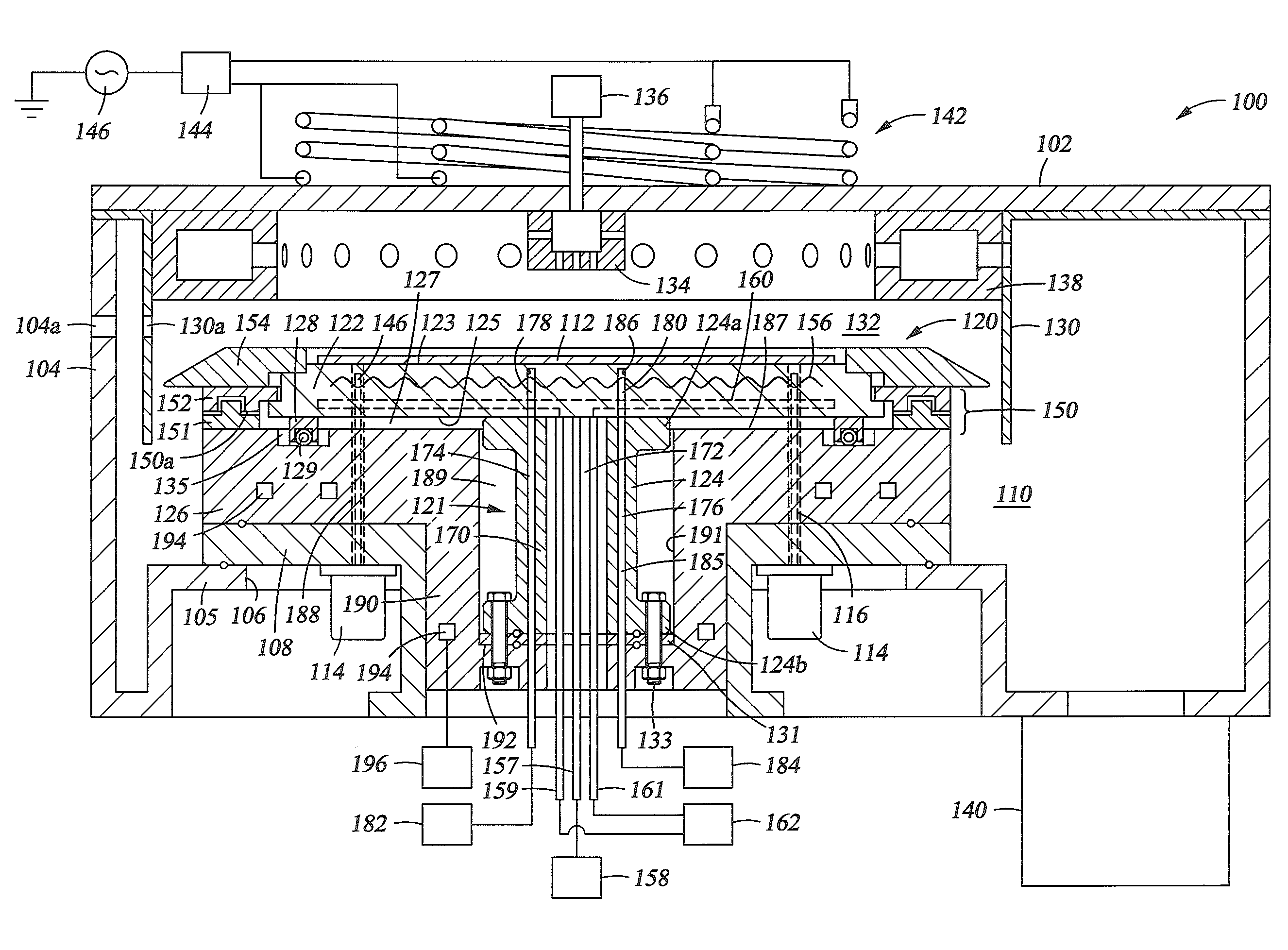
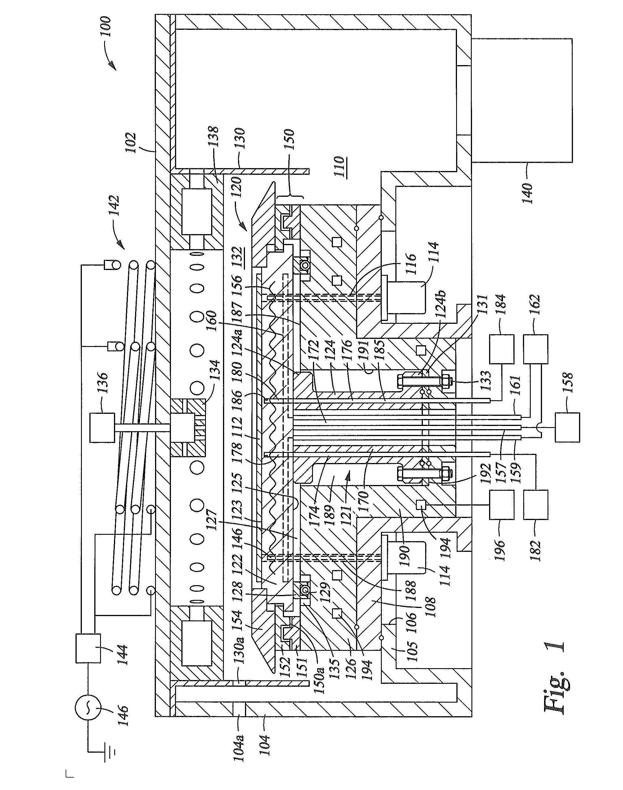
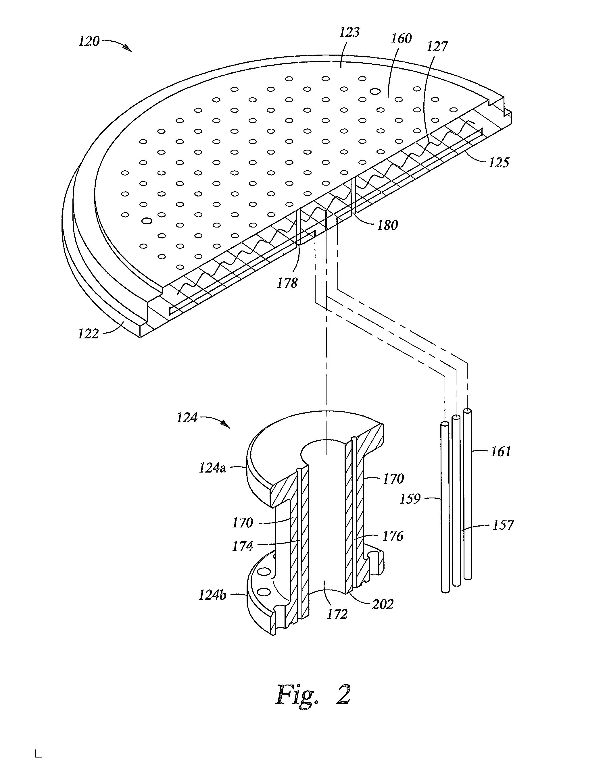
[0017]Embodiments of the present invention relate to apparatus and methods for supporting a substrate in a processing chamber operating at elevated temperatures. More particularly, embodiments of the present invention provide an electrostatic chuck assembly for operating at elevated temperatures. One embodiment provides a dielectric chuck body having a dielectric disk and a shaft extending from the dielectric disk. The shaft is hollow and has a central opening providing passage for connectors to an RF, a DC or an RF / DC combined electrode and / or heating elements embedded in dielectric disk. The shaft also has one or more channels formed through a sidewall along the axial direction. The one or more channels may be used to provide integrated passages for cooling fluids and / or substrate sensor passages or connections. By using the channels formed in the sidewall of the shaft, embodiments of the present invention avoid sealing cooling fluid passages using o-rings which may not withstand ...


PUM

PropertyMeasurementUnit
temperaturesaaaaaaaaaa
temperatureaaaaaaaaaa

Abstract

Embodiments of the present invention provide electrostatic chucks for operating at elevated temperatures. One embodiment of the present invention provides a dielectric chuck body for an electrostatic chuck. The dielectric chuck body includes a substrate supporting plate having a top surface for receiving a substrate and a back surface opposing the top surface, an electrode embedded in the substrate supporting plate, and a shaft having a first end attached to the back surface of the substrate supporting plate and a second end opposing the first end. The second end is configured to contact a cooling base and provide temperature control to the substrate supporting plate. The shaft is hollow having a sidewall enclosing a central opening, and two or more channels formed through the sidewall and extending from the first end to the second end.

Description

CROSS-REFERENCE TO RELATED APPLICATIONS[0001]This application claims benefit of U.S. Provisional Patent Applications Ser. No. 61 / 638,857 filed Apr. 26, 2012, Ser. No. 61 / 639,228 filed Apr. 27, 2012 and Serial No. 61 / 639,719 filed Apr. 27, 2012. The aforementioned patent applications are herein incorporated by reference.BACKGROUND[0002]1. Field[0003]Embodiments of the present invention generally relate to apparatus and methods for processing substrate at high temperature. Particularly, embodiments of the present invention relate to apparatus and methods for supporting a substrate in a processing chamber operating at high temperatures.[0004]2. Description of the Related Art[0005]Electrostatic chucks are commonly used in supporting and securing a substrate in a processing chamber. An electrostatic chuck generally has a non-conductive body, such as a ceramic body, having an embedded DC electrode for generating chucking force. One or more heating element may be included in the substrate ...

Claims


Application Information

Patent Timeline
Patent Type & Authority Applications(United States)
IPC IPC(8): H02N13/00
CPCH02N13/00H01L21/67103H01L21/67109H01L21/67248H01L21/6831H01L21/68792B23B31/28
Inventor LUBOMIRSKY, DMITRYSUN, JENNIFER Y.THACH, SENHLIN, XINGWILLWERTH, MICHAEL D.MAKHRATCHEV, KONSTANTIN
Owner APPLIED MATERIALS INC
Why Eureka
Try Eureka