Electronic element

a technology of electronic elements and thin films, applied in the field of thin film electronic elements, can solve the problems of difficult folding of conductive layers, affecting the life span of electronic elements, and unsatisfactory mechanical and chemical properties

Active Publication Date: 2013-10-31
BEIJING FUNATE INNOVATION TECH
View PDF15 Cites 2 Cited by
  • Summary
  • Abstract
  • Description
  • Claims
  • Application Information

AI Technical Summary

Benefits of technology

The patent text describes a problem with conventional thin film electronic elements that have conductive layers made of metal or metal oxide. These layers are difficult to fold and have poor mechanical and chemical properties, which affects the life spans of the electronic elements. The methods used to form these layers require high-temperature annealing, which can damage the substrate on which the electronic element is formed. This reduces the usefulness of these electronic elements. The technical effect of the patent is to offer an alternative to conventional methods that can address these issues and provide more durable and reliable thin film electronic elements.

Problems solved by technology

The conductive layers are difficult to fold, and the mechanical and chemical properties are not ideal.
As such, the life spans of the electronic elements are affected.
These methods need a process of high-temperature annealing, which will damage the substrate on which the electronic element is formed.
Thus, the life spans of the electronic elements are short.

Method used


Image

  • Electronic element
  • Electronic element
  • Electronic element

Examples


Embodiment Construction

[0016]The disclosure is illustrated by way of example and not by way of limitation in the figures of the accompanying drawings in which like references indicate similar elements. It should be noted that references to “an” or “one” embodiment in this disclosure are not necessarily to the same embodiment, and such references mean at least one.

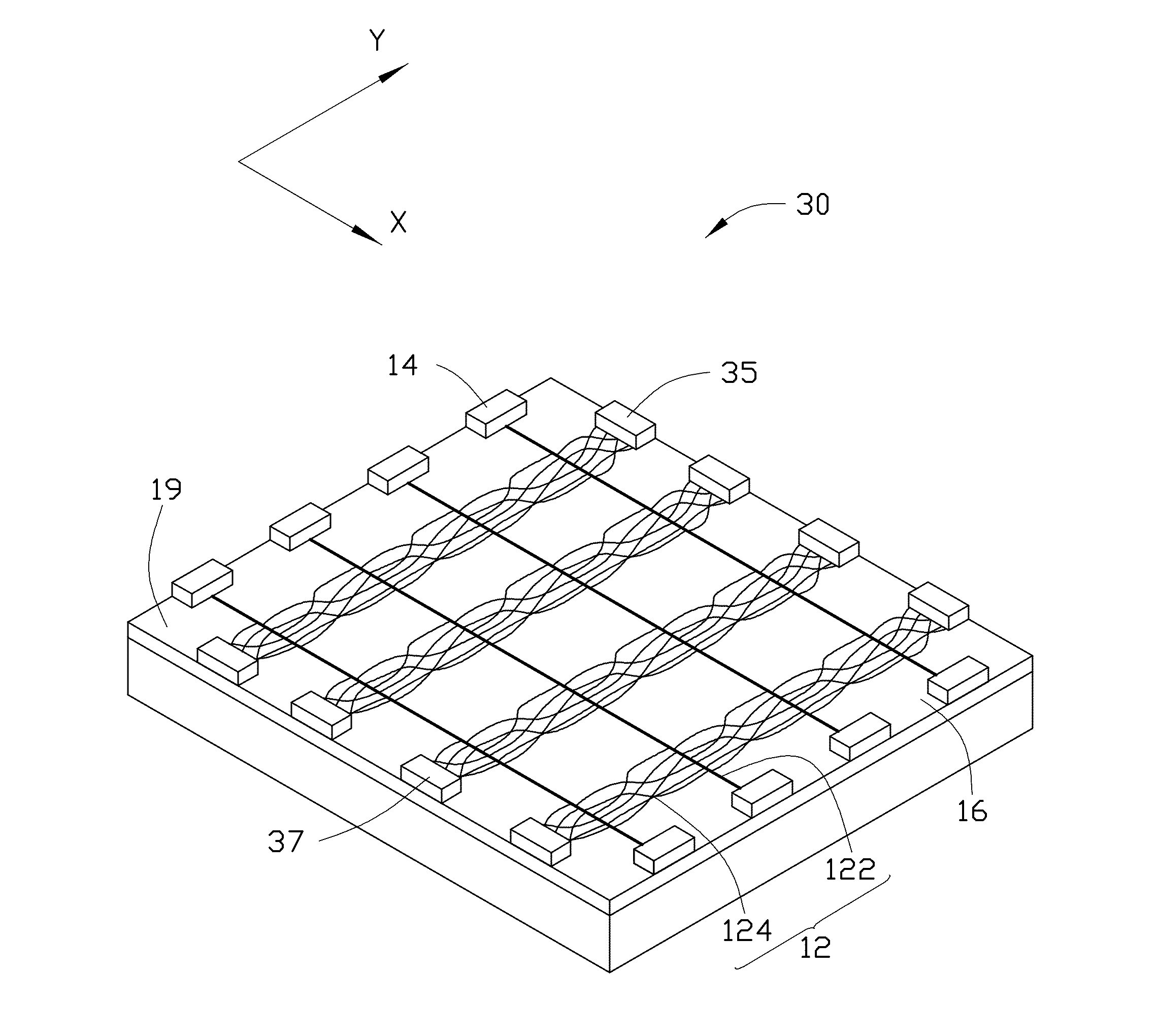
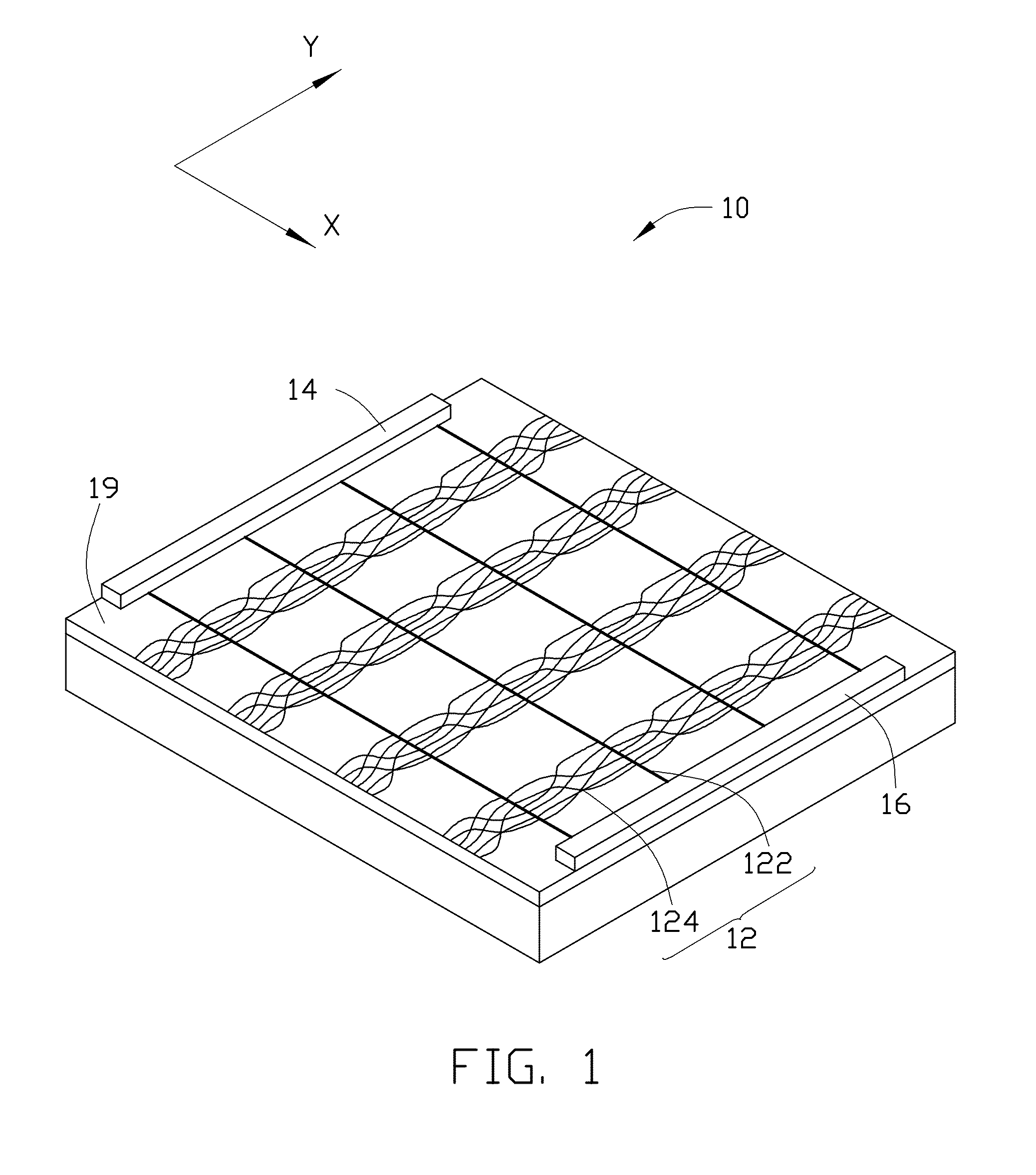
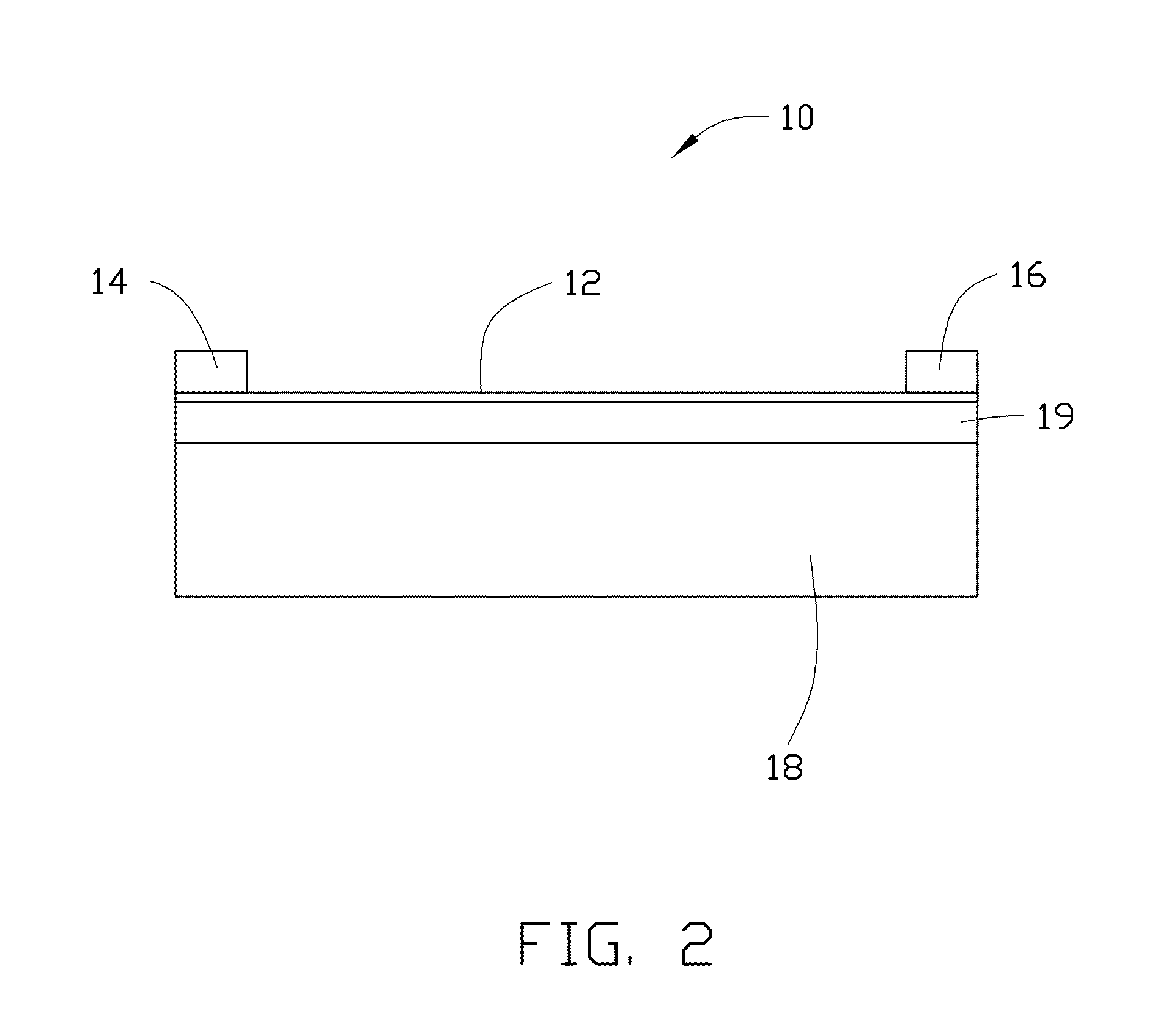
[0017]Referring to FIG. 1 and FIG. 2, one embodiment of an electronic element 100 includes a carbon nanotube film 12, a first electrode 14 and a second electrode 16 spaced from the first electrode 14. The first electrode 14 and the second electrode 16 are electrically connected with the carbon nanotube film 12.

[0018]The carbon nanotube film 12 includes a number of carbon nanotube linear units 122 and a number of carbon nanotube groups 124. The carbon nanotube linear units 122 are spaced from each other. The carbon nanotube groups 124 join with the carbon nanotube linear units 122 by van der Waals force. The carbon nanotube groups 124 located betw...


PUM


Abstract

An electronic element includes a carbon nanotube film, at least one first electrode and at least one second electrode spaced from the at least one first electrode. The carbon nanotube film includes a number of carbon nanotube linear units spaced from each other, and a number of carbon nanotube groups. The carbon nanotube linear units extend along a first direction to form a number of first conductive paths. The carbon nanotube groups are combined with the carbon nanotube linear units by van der Waals force in a second direction intercrossed with the first direction, to form a number of second conductive paths. The carbon nanotube groups between adjacent carbon nanotube linear units are spaced from each other in the first direction. The at least one first and second electrodes are electrically connected with the carbon nanotube film through the first conductive paths or the second conductive paths.

Description

RELATED APPLICATIONS[0001]This application claims all benefits accruing under 35 U.S.C. §119 from China Patent Application No. 201210122623.7, filed on Apr. 25, 2012 in the China Intellectual Property Office, the disclosure of which is incorporated herein by reference.BACKGROUND[0002]1. Technical Field[0003]The present disclosure relates to electronic elements, and particularly to an electronic element based on carbon nanotubes.[0004]2. Discussion of Related Art[0005]Electronic elements, especially thin film electronic elements, are important elements in various electronic devices, such as touch panels, liquid crystal display devices, or field emission display devices.[0006]Conventional thin film electronic elements usually includes electrically conductive layers, which mainly consist of metal or metal oxide, such as silver (Ag), copper (Cu), gold (Au), indium-tin oxide (ITO), or zinc oxide (ZnO). The conductive layers are difficult to fold, and the mechanical and chemical propertie...

Claims


Application Information

Patent Timeline
IPC IPC(8): H05K1/09
CPCH05K1/09B82Y30/00H01B1/04Y10S977/742
Inventor FENG, CHENQIAN, LIWANG, YU-QUAN
Owner BEIJING FUNATE INNOVATION TECH
Why Eureka
Try Eureka