Park lock for narrow transmission

a technology of narrow transmission and lock mechanism, which is applied in mechanical equipment, transportation and packaging, brake systems, etc., can solve the problems of tight space and weight budget of evs system, transmission should not provide too great mechanical resistance to mode transition, and implementation of such conventional solutions

Active Publication Date: 2013-10-31
TOYOTA JIDOSHA KK +1
View PDF1 Cites 21 Cited by
  • Summary
  • Abstract
  • Description
  • Claims
  • Application Information

AI Technical Summary

Benefits of technology

[0005]Disclosed is a system and method for a park lock mechanism for narrow transmissions having tight packaging and weight constraints. A novel architecture reduces part count to implement a robust one-dimensional remotely-actuated self-aligning park lock device in a narrow transmission that is appropriate for use in an electric vehicle or the like.
[0009]There are a number of features, benefits, and advantages of the present invention, with implementations of the present invention including reduced stresses and fewer mounting requirements for the park lock device components. Some features include including use of a self-aligning park sleeve that does not experience any net moment under parked load, a bracket simply retains both the park sleeve and pawl stopper within alignment limits, and provides safe operation in a parked mode and a not parked mode.

Problems solved by technology

Where many conventional park lock devices are implemented in two planes, a narrow transmission of an electric vehicle prevents implementation of such conventional solutions.
Irrespective of a slope on which the EV is stopped, the transmission should not provide too great of mechanical resistance to mode transition.
While not necessarily required by the narrowness of the EV transmission, systems on EVs have tight budgets for space and weight.
These budget constraints work against a straight-forward implementation of a park lock device for a narrow transmission such as may be contemplated to be used in an EV.

Method used


Image

  • Park lock for narrow transmission
  • Park lock for narrow transmission
  • Park lock for narrow transmission

Examples


Embodiment Construction

[0025]Embodiments of the present invention provide a system and method for a park lock mechanism for narrow transmissions having tight packaging and weight constraints. The following description is presented to enable one of ordinary skill in the art to make and use the invention and is provided in the context of a patent application and its requirements.

[0026]Various modifications to the preferred embodiment and the generic principles and features described herein will be readily apparent to those skilled in the art. Thus, the present invention is not intended to be limited to the embodiment shown but is to be accorded the widest scope consistent with the principles and features described herein.

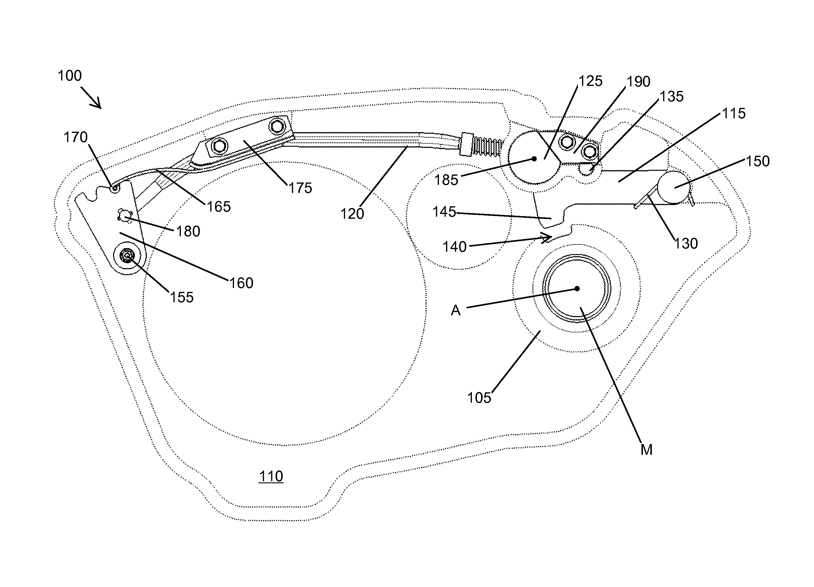
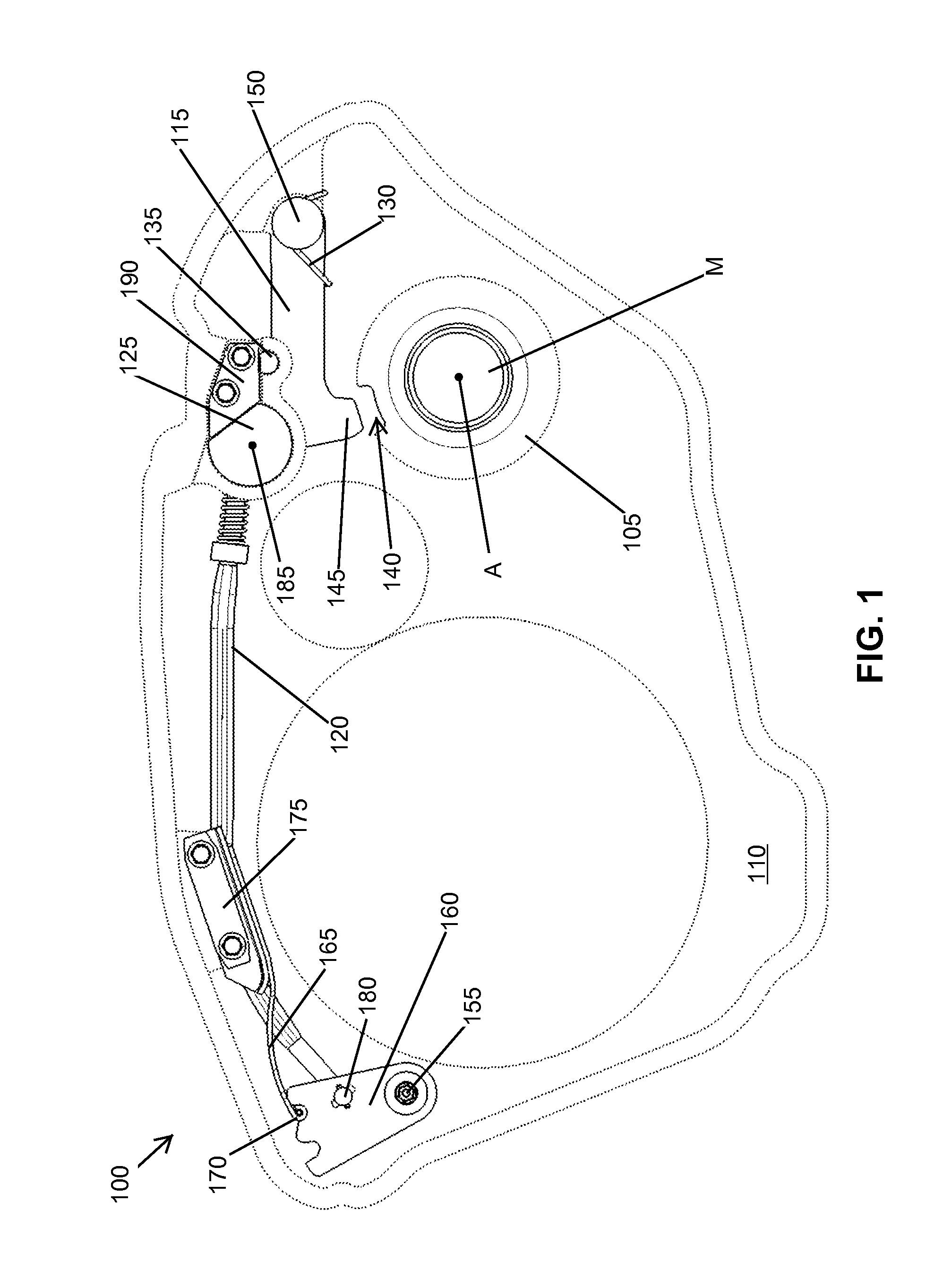
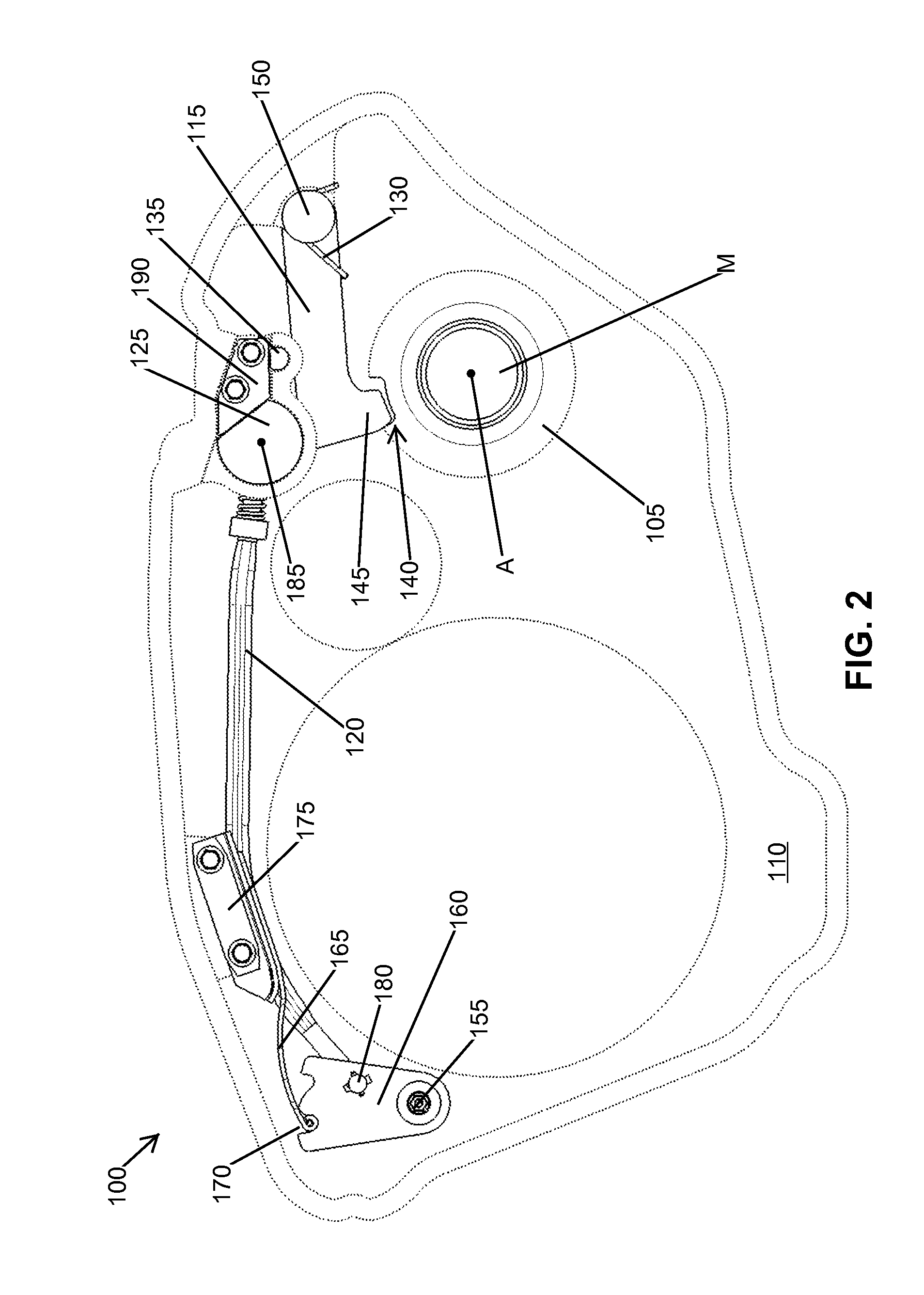
[0027]FIG. 1 illustrates a side view of a narrow transmission 100 including a park lock device, the park lock device in a “not parked” mode or position, and FIG. 2 illustrates a side view of narrow transmission 100 including the park lock device in a “parked” mode or position. The park lock...


PUM


Abstract

A park lock of a transmission, including a park gear; a park pawl rotating about a pawl shaft, the park pawl having a pawl portion locking the park gear, the park pawl including a cam contact portion; a park rod responsive to an operation of a controller, the park rod having a cam portion pressing the cam contact portion to have park pawl engage the park gear; a park sleeve receiving the cam portion and defining a first contact point providing a reactive force to the cam contact portion of the park pawl pressing against the cam portion at a second contact point; a pawl torsional spring biasing the park pawl towards disengagement; and a pawl stopper limiting the rotation of the park pawl wherein motions are constrained within a plane of the transmission and components are rotatingly disposed in parallel axis bores in one half of a transmission case.

Description

BACKGROUND OF THE INVENTION[0001]The present invention relates generally to mechanical park locking for vehicle transmissions, and more specifically, but not exclusively, to a park lock mechanism for narrow transmissions having tight packaging and weight constraints.[0002]Park lock devices for automotive vehicle transmissions are notoriously well known as a general proposition. Transmissions have continued to evolve, and park lock devices disposed within such transmissions also need to evolve. For example, a particular transmission for an electric vehicle (EV) is quite narrow as it is positioned between an electric motor on one side and an inverter on the other side. Where many conventional park lock devices are implemented in two planes, a narrow transmission of an electric vehicle prevents implementation of such conventional solutions. Further, many conventional park lock devices include a park lock controller near the parking gear. The narrow transmission having large areas cover...

Claims


Application Information

Patent Timeline
Patent Type & Authority Applications(United States)
IPC IPC(8): B60W10/196
CPCB60T1/062F16H63/3425Y10T74/19637
Inventor BARTON, AUGUSTO E.FONG, WILLIAM RANDALLPINKLEY, GARY ALLENPEARCE, JR., EDWIN MARCUMMORISAWA, KUNIOKANEKO, KAZUNORITANAKA, KOICHI
Owner TOYOTA JIDOSHA KK
Why Eureka
Try Eureka