Fast-speed laser scoring method

a laser scoring and laser scoring technology, applied in laser beam welding equipment, manufacturing tools, welding equipment, etc., can solve the problems of hysteresis iron loss rising, iron loss dropping, and fine width of major magnetic domain of oriented silicon steel sheets, so as to reduce iron loss by scoring lines, reduce iron loss by 10%, and reduce iron loss easily

Active Publication Date: 2013-10-31
BAOSHAN IRON & STEEL CO LTD
View PDF4 Cites 5 Cited by
  • Summary
  • Abstract
  • Description
  • Claims
  • Application Information

AI Technical Summary

Benefits of technology

[0016]1. By superposing closed magnetic domain of the upper and lower surfaces of silicon steel sheet, it is possible to further fine magnetic domain and so to attain the goal to reduce iron loss by scored lines.
[0017]2. The scoring method of the invention is able to simultaneously score lines on both the upper surface and the lower surface of an oriented silicon steel strip with the biggest space between every two adjacent scored lines being up to 12 mm, and able to easily reduce iron loss by 10%. Contrarily, conventional scoring methods can only score lines on one surface of a silicon steel sheet at a time and its widest space between every two adjacent scored lines can not be beyond 6 mm in order to reduce iron loss by 10%. That is to say, to get the same result of reducing iron loss, the scoring speed of the invention's method is 1.

Problems solved by technology

Hence, as the space between every two adjacent scored lines is reduced, the width of major magnetic domain of oriented silicon steel sheet is got fined and iron loss of it drops down.
However, wh

Method used


Image

  • Fast-speed laser scoring method
  • Fast-speed laser scoring method
  • Fast-speed laser scoring method

Examples


Embodiment Construction

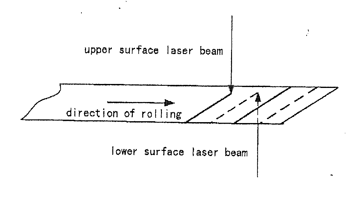
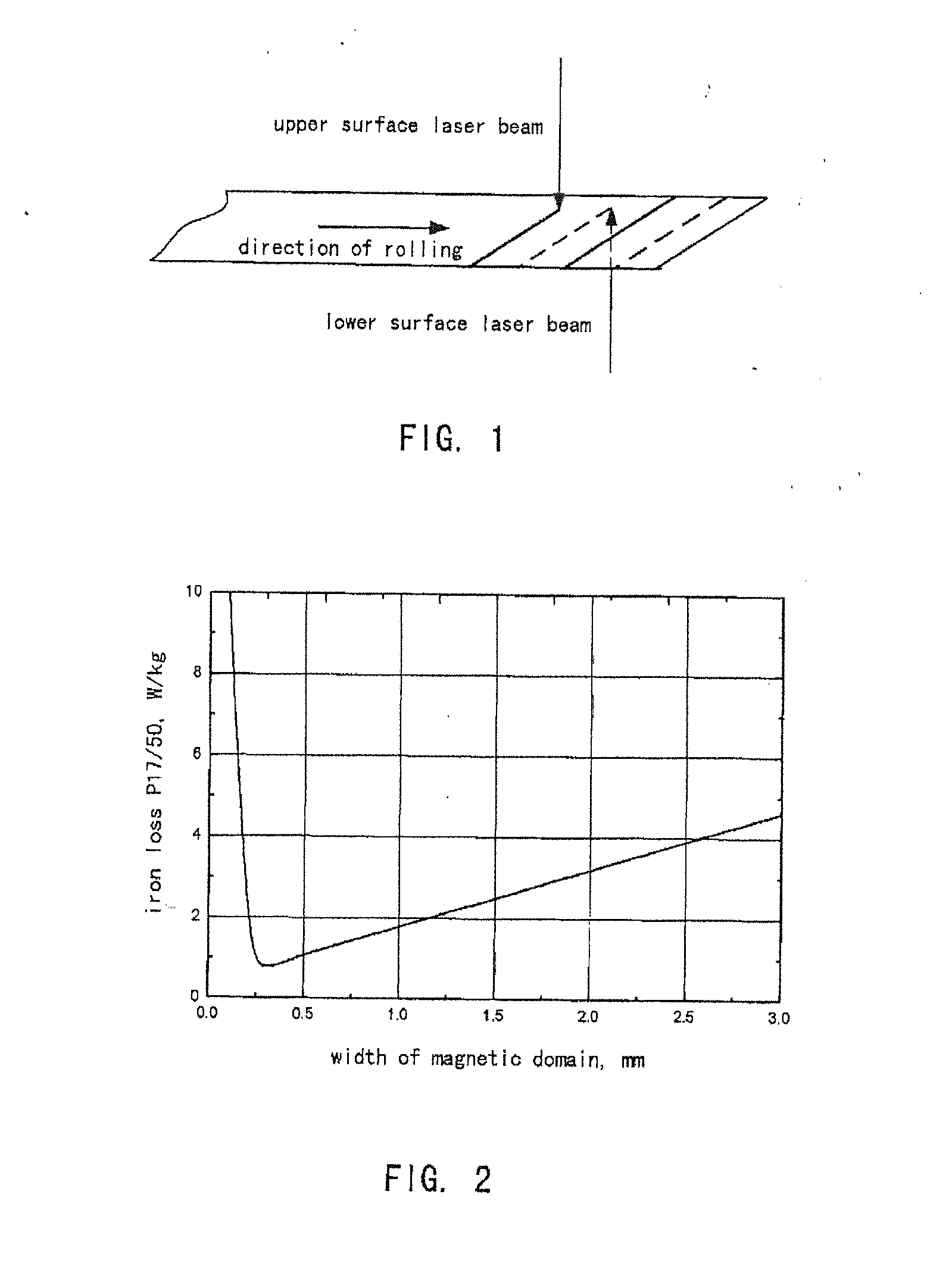
[0023]The invention is now described in detail in reference to the accompanying drawings and the embodiments.

[0024]Referring to FIG. 1, the fast-speed laser scoring method employs a laser scoring device and is able to simultaneously score lines on both the upper and lower surfaces of an oriented silicon steel strip which is being fed and traveling forwards on a production line with high-focalized continuous wave laser beam. The lines scored on the upper surface and the lines scored on the lower surface have the same space between every two adjacent scored lines but are staggered with respect to each other in order to reduce iron loss evenly. The space between every two adjacent scored lines on the same surface is 6-12 mm, laser power is 1000-3000 W, and scanning speed is 100-400 m / min.

[0025]Let's take it for example to describe that to use CO2 gas continuous wave laser with 10.6 μm wave length and double laser projectors to make scoring simultaneously on each side of the strip steel...


PUM

PropertyMeasurementUnit
Poweraaaaaaaaaa
Lengthaaaaaaaaaa
Speedaaaaaaaaaa

Abstract

A fast-speed laser scoring method is provided, in which a set of related laser scoring device is used to simultaneously score lines on the upper surface and the lower surface of an oriented silicon steel strip, which is being fed and traveling forwards on a production line, with high-focalized continuous wave laser beam; the lines scored on the upper surface and the lines scored on the lower surface have the same space between every two adjacent scored lines but are staggered each other in order to reduce iron loss evenly. The space between every two adjacent scored lines on the same surface is 6-12 mm, laser power is 1000-3000 W and scanning speed is 100-400 m/min. The machining rate of the scoring method and device attains 1.5-2 times the one of conventional scoring methods which can not simultaneously score the upper and lower surfaces of a steel strip at a time. The lines scored on a steel strip by the method can reduce iron loss of the strip by 10-16%.

Description

FIELD OF THE INVENTION[0001]This invention relates generally to a laser scoring method, and particularly, to a fast-speed laser scoring method. By this laser scoring method, it is possible to simultaneously score lines on both the upper surface and the lower surface of a steel strip so as to raise machining rate of a laser scoring machine and to raise the contribution of the scored lines to reduce iron loss of the steel strip.BACKGROUND OF THE INVENTION[0002]Oriented silicon steel sheets are essential material for manufacturing various transformers. A transformer consumes electric power because of its iron loss. For this reason, to reduce iron loss is an ever-seeking target in production of oriented silicon steel sheets. Iron loss of silicon steel sheets is divided into hysteresis loss and eddy current loss. The eddy current loss is subdivided into classical eddy current loss (caused by eddy current) and abnormal eddy current loss (caused by magnetic domain wall movement and proport...

Claims


Application Information

Patent Timeline
IPC IPC(8): B23K26/36
CPCB23K26/365C21D1/38C21D8/12C21D8/1294C21D2201/05B23K26/361B23K26/359C21D10/005B23K26/362
Inventor HUANG, WANGYALI, GUOBAOZHANG, XINQIANGMAO, XINGGUO, WANQINGZHU, JIANRUXIANG, BANGLIN
Owner BAOSHAN IRON & STEEL CO LTD
Why Eureka
Try Eureka