
Electric energy storage system comprising an inverter

a technology of electric energy storage and inverter, which is applied in the direction of energy storage emission reduction, dc source parallel operation, ac network load balancing, etc., can solve the problems of increasing the number of inverters to be used, the voltage level of certain electric energy storage units may be incompatible with the voltage level, and the need for additional adapter components, etc., to optimize the cost and size of the used semiconductors, cost and complexity optimization

Active Publication Date: 2013-10-31
SAFT GRP SA
View PDF12 Cites 67 Cited by
  • Summary
  • Abstract
  • Description
  • Claims
  • Application Information

AI Technical Summary

Benefits of technology

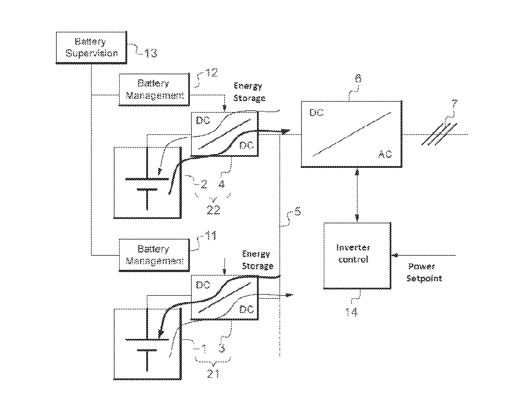
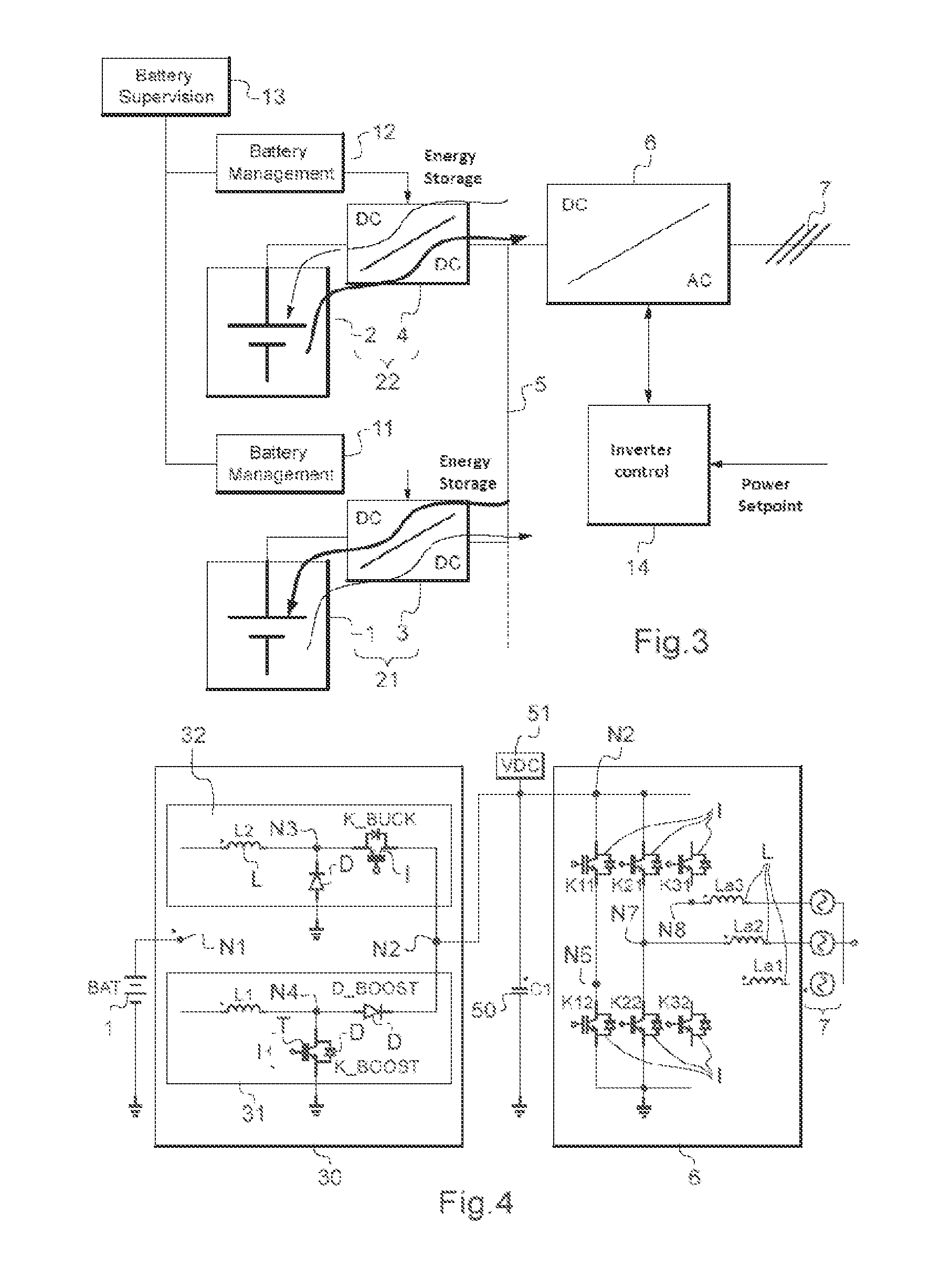
The invention is about an electric energy storage system that simplifies and reduces costs by using a shared inverter and multiple choppers to connect multiple energy storage units in parallel. The system also includes a DC bus that simplifies energy exchange between the units. The technical effects are a more efficient and cost-effective electric energy storage system.

Problems solved by technology

The problem then arises of the number of inverters to be used and how to connect the inverter(s) to the electric energy storage units.
Additionally, the voltage level of certain electric energy storage units may be incompatible with the voltage level of the AC network and may require additional adapter components.
One drawback of this first prior art is the complexity and overall cost of the electric energy storage system, as it comprises several inverters, the inverter being a relatively complex and expensive component.
Although using a shared inverter, oversized relative to each of the choppers that are connected in parallel to its input, makes it possible to save in terms of cost and complexity, the addition of several choppers nevertheless creates losses in terms of cost and increased complexity.
Further, the use of complex choppers comprising many power switches reduces the effectiveness of the power balance.
Although using a shared inverter, oversized relative to each of the choppers that are connected in parallel to its input, makes it possible to save in terms of cost and complexity, the addition of several choppers nevertheless creates losses in terms of cost and increased complexity.

Method used


Image

  • Electric energy storage system comprising an inverter
  • Electric energy storage system comprising an inverter
  • Electric energy storage system comprising an inverter

Examples


Embodiment Construction

[0046]The electric energy storage units are often batteries. An electric energy storage unit may be a battery, part of a battery, or a group of batteries. In the rest of the text, the term battery will be used indifferently with the expression electric energy storage unit. The batteries used may use the same technology or different technologies. A battery may be replaced by another type of electric energy storage unit, for example a supercapacitor.

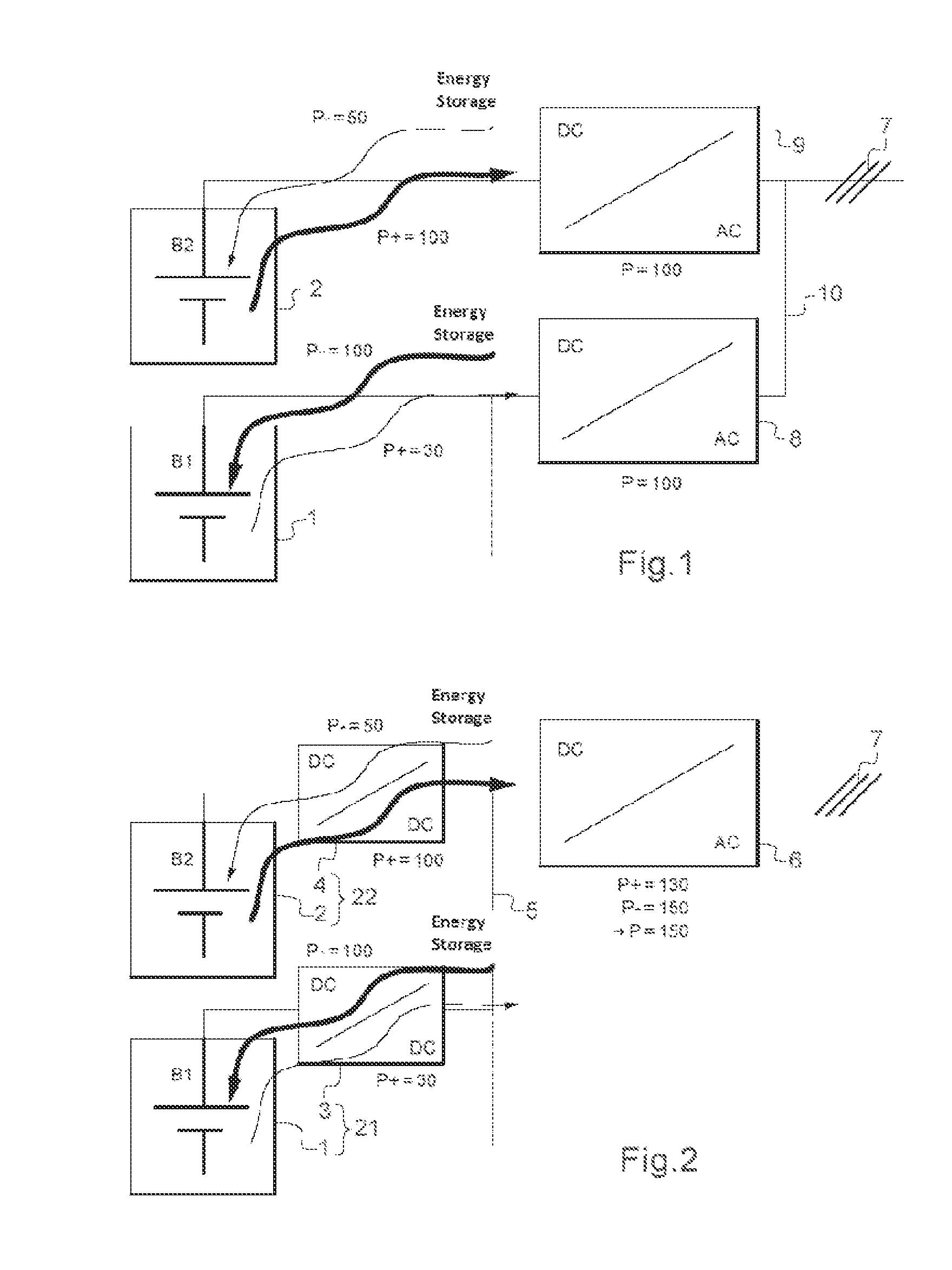
[0047]A bidirectional chopper may be symmetrical or asymmetrical, while an inverter is symmetrical. An asymmetrical bidirectional chopper is an asymmetrically-sized chopper. The power switches of an asymmetrical bidirectional chopper may therefore have different sizes, some used for a usage direction being smaller, i.e., charge or discharge, of the battery, relative to other(s) used in the other direction that will be larger. The power switches of an inverter are the same size in both directions; they are furthermore preferably all the sam...


PUM


Abstract

The invention relates to an electric energy storage system, comprising an inverter (6), several associations (21, 22), of an electric energy storage unit (1, 2) in series with a bidirectional chopper (3, 4), connected in parallel to a same input of the inverter (6), on the side of their chopper (3, 4), characterized in that at least one bidirectional chopper (3, 4), associated with an electric energy storage unit (1, 2) that can be charged and discharged asymmetrically, is sized asymmetrically for the charge and discharge of said associated storage unit (1, 2).

Description

BACKGROUND OF THE INVENTION[0001]The present invention relates to the field of electric energy storage systems comprising an inverter. These energy storage systems comprise electric energy storage units and are often coupled to an AC network to store electric energy when the AC network has too much or does not need any and to restore the electric energy to the AC network when it needs it. This excess electric energy, which is temporarily stored in the electric energy storage system to then be provided to the AC network, may either come from the AC network or from energy sources, which are preferably renewable, for example such as solar panels or wind turbines.[0002]In an electric energy storage system of a certain size, which must be connected to an AC network, several electric energy storage units are used. These electric energy storage units may be used individually, in a group or in their entirety, at a given moment, depending on the needs of the AC network. At least one inverter...

Claims


Application Information

Patent Timeline
Patent Type & Authority Applications(United States)
IPC IPC(8): H02J1/10
CPCH02J1/10H02J3/32H02M3/1582H02M3/1584Y02P90/50H02J7/02H02J2207/20
Inventor JAOUI, YOUNESMORIN, CHRISTOPHE
Owner SAFT GRP SA
Learn More