Structured plane illumination microscopy

a structured plane and microscopy technology, applied in the field of microscopy, can solve the problems of fluorescent molecules that cannot be optically excited for only a limited period of time, the cost of slower speed, and the inability to achieve fast speed

Active Publication Date: 2013-10-31
HOWARD HUGHES MEDICAL INST
View PDF23 Cites 150 Cited by
  • Summary
  • Abstract
  • Description
  • Claims
  • Application Information

AI Technical Summary

Problems solved by technology

The resulting images exhibit less out-of-focus background information on thick samples than is the case in widefield microscopy, but at the cost of slower speed, due to the requirement to scan the focus across the entire plane of interest.
One limitation of fluorescence imaging, however, is that fluorescent molecules can be optically excited for only a limited period of time before they are permanently extinguished (i.e., “photobleach”).
Not only does such bleaching limit the amount of information that can be extracted from the specimen, it can also contribute to photo-induced changes in specimen behavior, phototoxicity, or even cell death.
Unfortunately, both widefield and confocal microscopy excite fluorescence in every plane of the specimen, whereas the information rich, high resolution content comes only from the vicinity of the focal plane.
Thus, both widefield and confocal microscopy are very wasteful of the overall fluorescence budget and potentially quite damaging to live specimens.
Furthermore, the high intensities required for TPFE can give rise to other, nonlinear mechanisms of photodamage in addition to those present in the linear methods of widefield and confocal microscopy.
A principal limitation of these implementations is that, due to the diffraction of light, there is a tradeoff between the XY extent of the illumination across the focal plane of the imaging objective, and the thickness of the illumination in the Z direction perpendicular to this plane.

Method used


Image

  • Structured plane illumination microscopy
  • Structured plane illumination microscopy
  • Structured plane illumination microscopy

Examples


Embodiment Construction

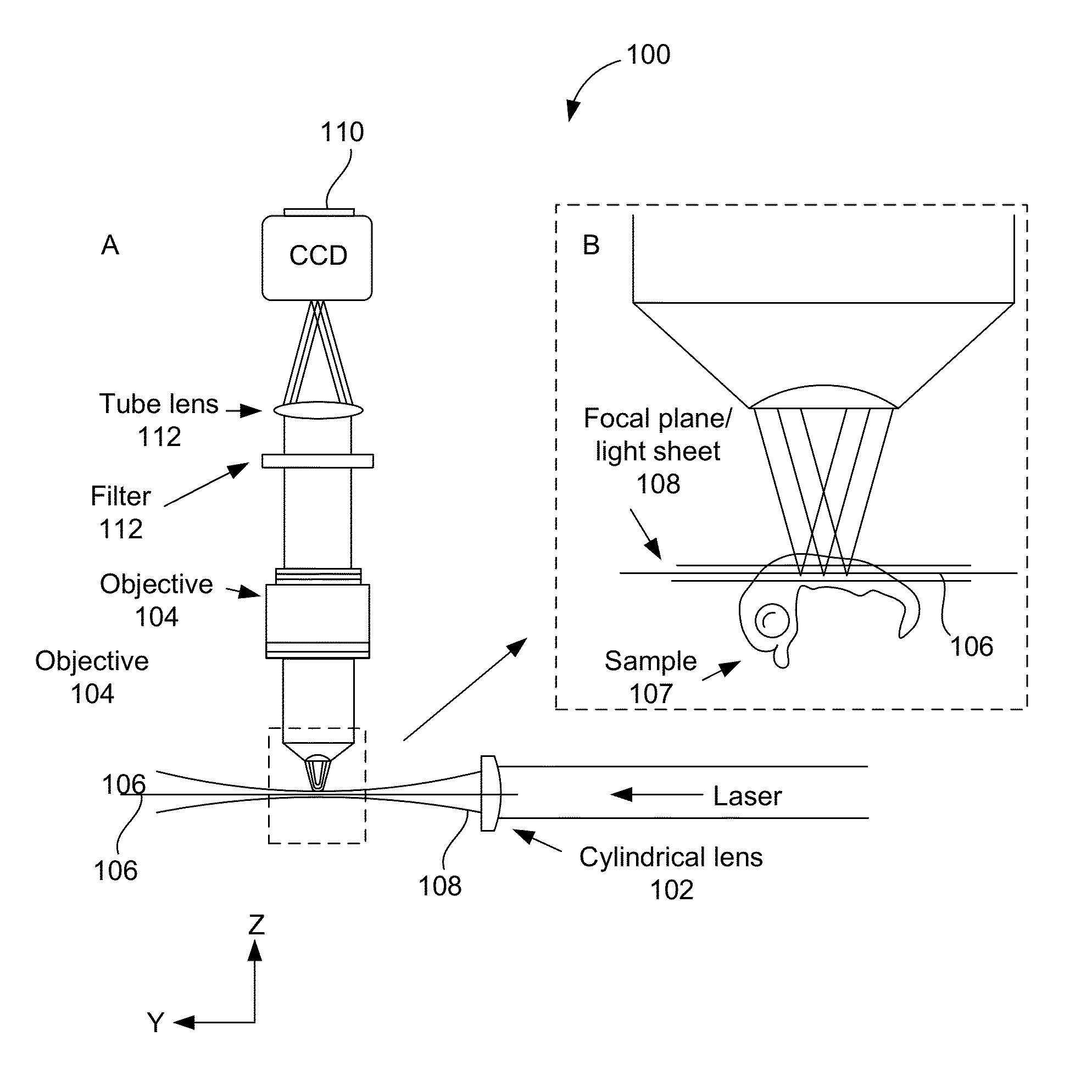
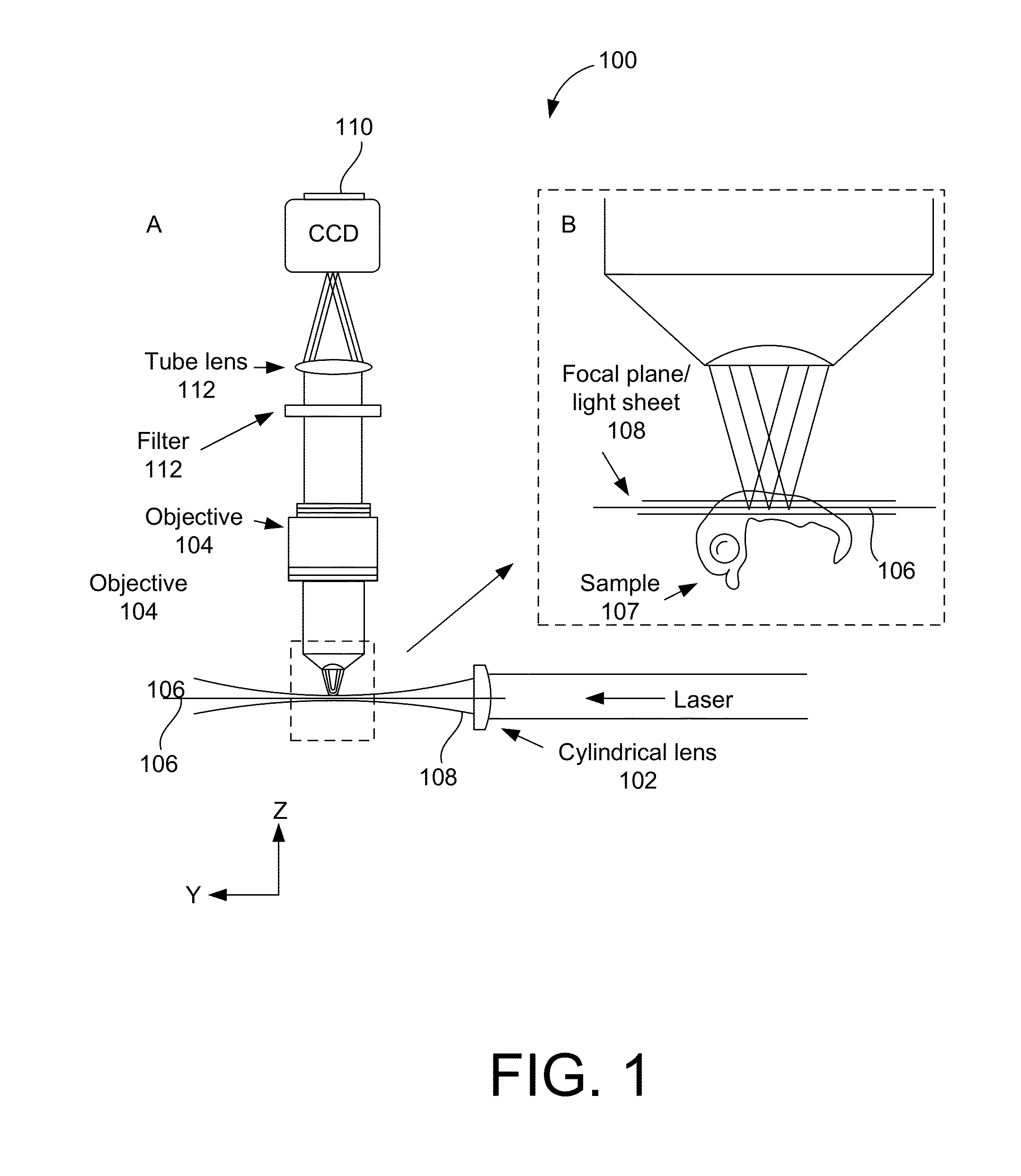
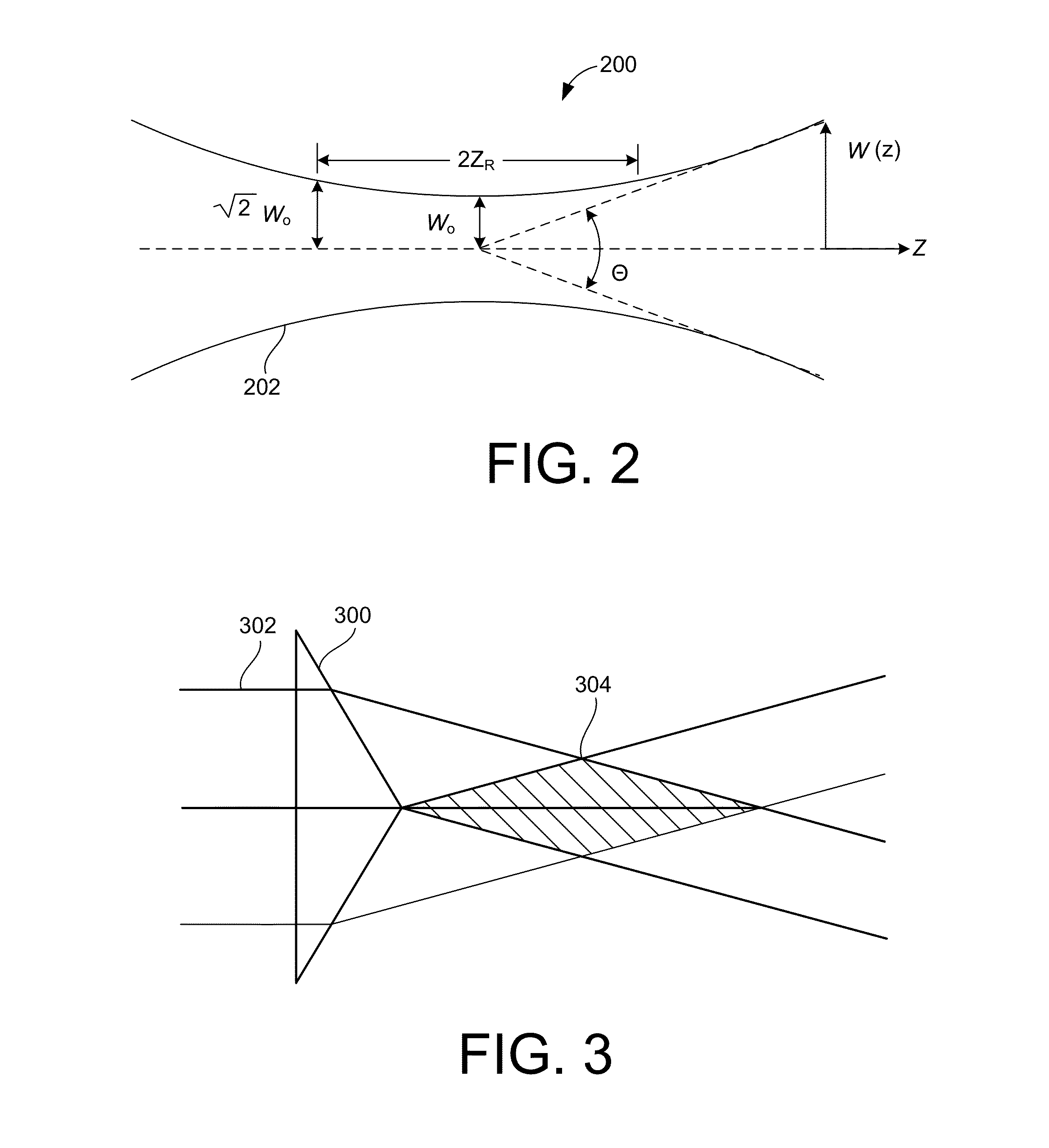
[0063]This description discloses microscopy and imaging apparatus, systems, methods and techniques, which enable a light sheet or pencil beam to have a length that can be decoupled from its thickness, thus allowing the illumination of large fields of view (e.g., tens or even hundreds of microns) across a plane having a thickness on the order of, or smaller than, the depth of focus of the imaging objective by using illumination beams having a cross-sectional field distribution that is similar to a Bessel function. Such illumination beams can be known as Bessel beams. Such beams are created by focusing light, not in a continuum of azimuthal directions across a cone, as is customary, but rather at a single azimuthal angle or range of azimuthal angles with respect to the axis of the focusing element. Bessel beams can overcome the limitations of the diffraction relationship shown in FIG. 2, because the relationship shown in FIG. 2 is only valid for lenses (cylindrical or objectives) that...


PUM


Abstract

An apparatus includes a light source configured for generating a coherent light beam having a wavelength, λ, a light detector, and beam-forming optics configured for receiving the generated light beam and for generating a plurality of substantially parallel Bessel-like beams directed into a sample in a first direction. Each of the Bessel-like beams has a fixed phase relative to the other Bessel-like beams. Imaging optics are configured for receiving light from a position within the sample that is illuminated by the Bessel-like beams and for imaging the received light onto the detector. The imaging optics include a detection objective having an axis oriented in a second direction that is non-parallel to the first direction, where the detector is configured for detecting light received by the imaging optics. A processor configured to generate an image of the sample based on the detected light.

Description

CROSS-REFERENCE TO RELATED APPLICATIONS[0001]This is a continuation-in-part of U.S. patent application Ser. No. 13 / 160,492, filed Jun. 14, 2011, entitled “BESSEL BEAM PLANE ILLUMINATION MICROSCOPE,” which, in turn, claims the priority of: U.S. Provisional Patent Application No. 61 / 354,532, filed Jun. 14, 2010, entitled “BESSEL BEAM PLANE ILLUMINATION MICROSCOPE”; U.S. Provisional Patent Application No. 61 / 386,342, filed Sep. 24, 2010, entitled “BESSEL BEAM PLANE ILLUMINATION MICROSCOPE”; and U.S. Provisional Patent Application No. 61 / 433,034, filed Jan. 14, 2011, entitled “BESSEL BEAM PLANE ILLUMINATION MICROSCOPE.” This application also claims priority to this application also claims priority to U.S. Provisional Patent Application No. 61 / 648,974, entitled “THREE-DIMENSIONAL IMAGING OF THICKLY FLUORESCENT LIVING SPECIMENS BEYOND THE DIFFRACTION LIMIT,” filed May 18, 2012. The subject matter of each of these earlier filed applications is hereby incorporated by reference.TECHNICAL FIE...

Claims


Application Information

Patent Timeline
Patent Type & Authority Applications(United States)
IPC IPC(8): H04N7/18
CPCH04N7/18G02B21/002G02B21/06G02B27/095
Inventor BETZIG, ROBERT E.WANG, KAI
Owner HOWARD HUGHES MEDICAL INST
Why Eureka
Try Eureka