Laser line probe that produces a line of light having a substantially even intensity distribution

a laser line and line light technology, applied in the field of laser line probes, can solve the problems of affecting the signal-to-noise ratio, the inability of modern llp cameras to handle extremely high contrast, and the cost-intensive and relatively difficult use of measurement installations

Inactive Publication Date: 2013-10-31
FARO TECH INC
View PDF7 Cites 32 Cited by
  • Summary
  • Abstract
  • Description
  • Claims
  • Application Information

AI Technical Summary

Problems solved by technology

Portable AACMMs represent a vast improvement over known stationary or fixed, cost-intensive and relatively difficult to use measurement installations, particularly in the amount of time it takes to perform dimensional measurements of relatively complex parts.
Cameras used by contemporary LLPs typically cannot handle the extremely high contrasts caused by a high laser light exposure and thus, a lower exposure setting is often used by the LLPs.
However, the use of a lower exposure sett...

Method used


Image

  • Laser line probe that produces a line of light having a substantially even intensity distribution
  • Laser line probe that produces a line of light having a substantially even intensity distribution
  • Laser line probe that produces a line of light having a substantially even intensity distribution

Examples


Embodiment Construction

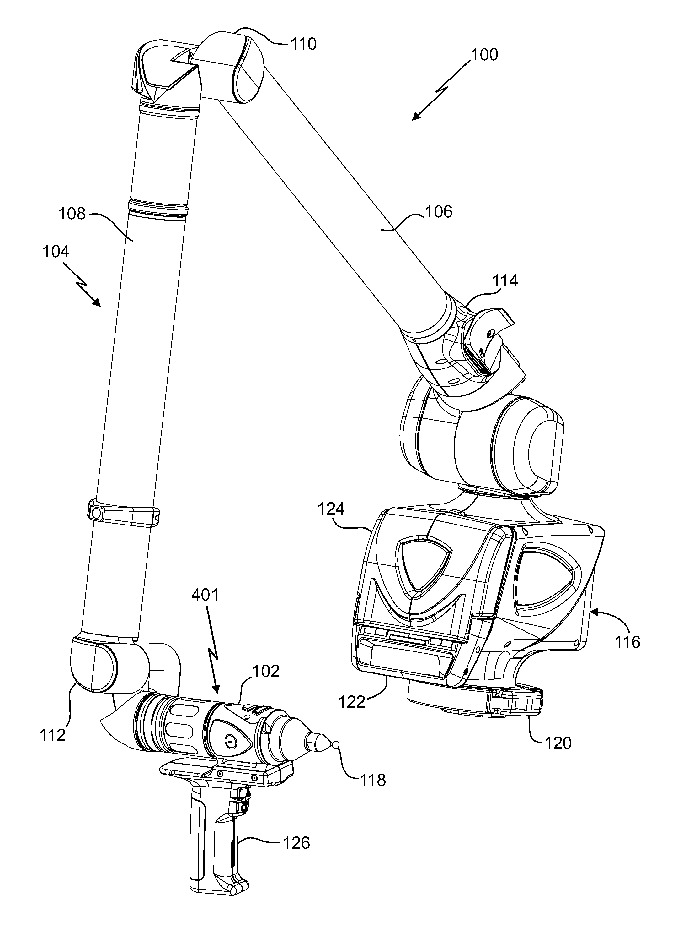
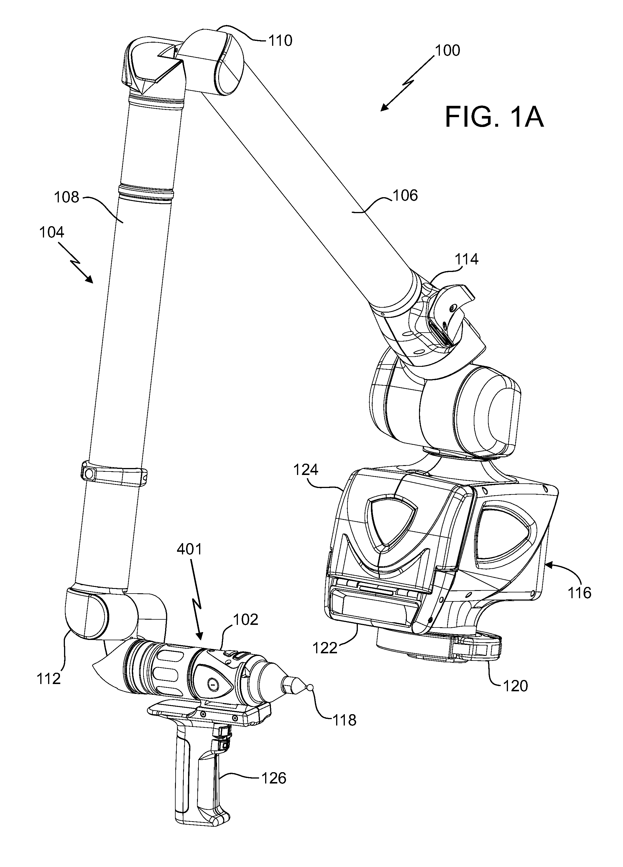
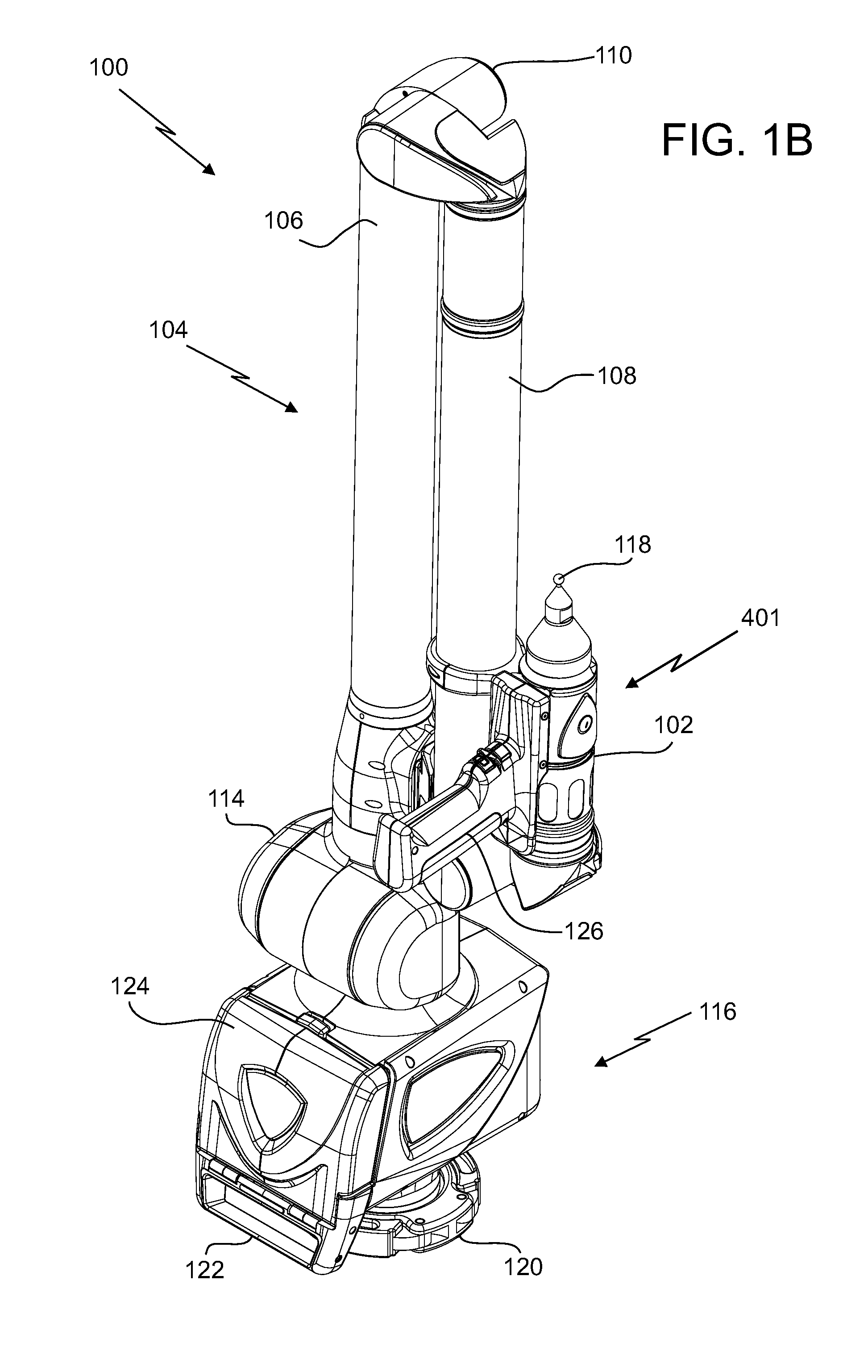
[0025]An embodiment of the present invention provides an enhanced laser line probe (LLP) that produces a line of light having a substantially even intensity distribution across the length of the line. The line of light produced by the LLP is projected onto an object and used by the LLP to measure the object. An embodiment utilizes a projector that includes a lens and a continuously varying neutral density filter. The lens scatters light from a light source into a substantially straight line having an uneven intensity distribution, and the continuously varying neutral density filter evens out the intensity distribution of the line prior to the line being projected onto the object. Thus, the line projected onto the object no longer exhibits a hot spot (i.e., high intensity) near the center of the line's length with reduced intensity towards the end points of the line as is typical when the line is generated using, for example, a lens such as a cylindrical lens such or a rod lens. Beca...


PUM


Abstract

A laser line probe (LLP) configured to measure an object is provided. The LLP includes a projector, a camera, a bracket, and an electronic circuit. The projector includes a light source, a first lens system and a continuously varying neutral density filter. The projector is configured for generating a line of light having a substantially even intensity distribution and for projecting the line of light onto the object. The camera includes a second lens system and a photosensitive array. The second lens system is configured to collect the light reflected by or scattered off the object as a first collected light and to image the first collected light onto the photosensitive array. The electronic circuit includes a processor and is configured to determine three-dimensional coordinates of a plurality of points of light projected on the object by the projector.

Description

CROSS REFERENCE TO RELATED APPLICATIONS[0001]The present application claims the benefit of U.S. patent application Ser. No. 13 / 721,169, filed Dec. 20, 2012, the contents of which are hereby incorporated by reference in its entirety.BACKGROUND[0002]The present disclosure relates generally to a laser line probe (LLP), and more particularly to a LLP that produces a line of light having a substantially even intensity distribution, which may be used for example, in conjunction with a portable articulated arm coordinate measuring machine (AACMM) or in a fixed (i.e., non-movable) inspection installation (e.g., an automobile assembly line).[0003]Portable AACMMs have found widespread use in the manufacturing or production of parts where there is a need to rapidly and accurately verify the dimensions of the part during various stages of the manufacturing or production (e.g., machining) of the part. Portable AACMMs represent a vast improvement over known stationary or fixed, cost-intensive and...

Claims


Application Information

Patent Timeline
IPC IPC(8): G01C11/02
CPCG01C11/02G01B5/008G01B11/03G01B11/2513
Inventor ATWELL, PAUL C.
Owner FARO TECH INC
Why Eureka
Try Eureka