Electrophotographic image forming apparatus
a technology of forming apparatus and photosensitive drum, which is applied in the direction of electrographic process apparatus, instruments, optics, etc., can solve the problems of abraded photosensitive drum and developing roller, increased number of revolutions of developing roller, and earlier reaches the end of life of developing roller. , to achieve the effect of suppressing the shortening of the life of the developing roller
- Summary
- Abstract
- Description
- Claims
- Application Information
AI Technical Summary
Benefits of technology
Problems solved by technology
Method used
Image
Examples
first embodiment
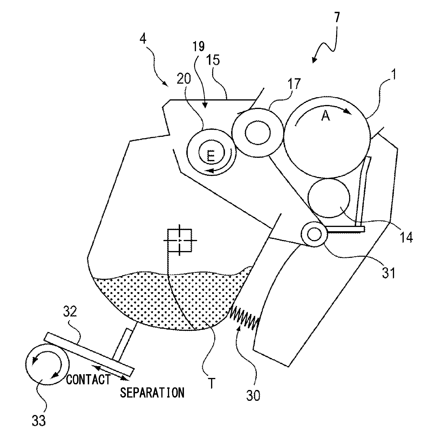
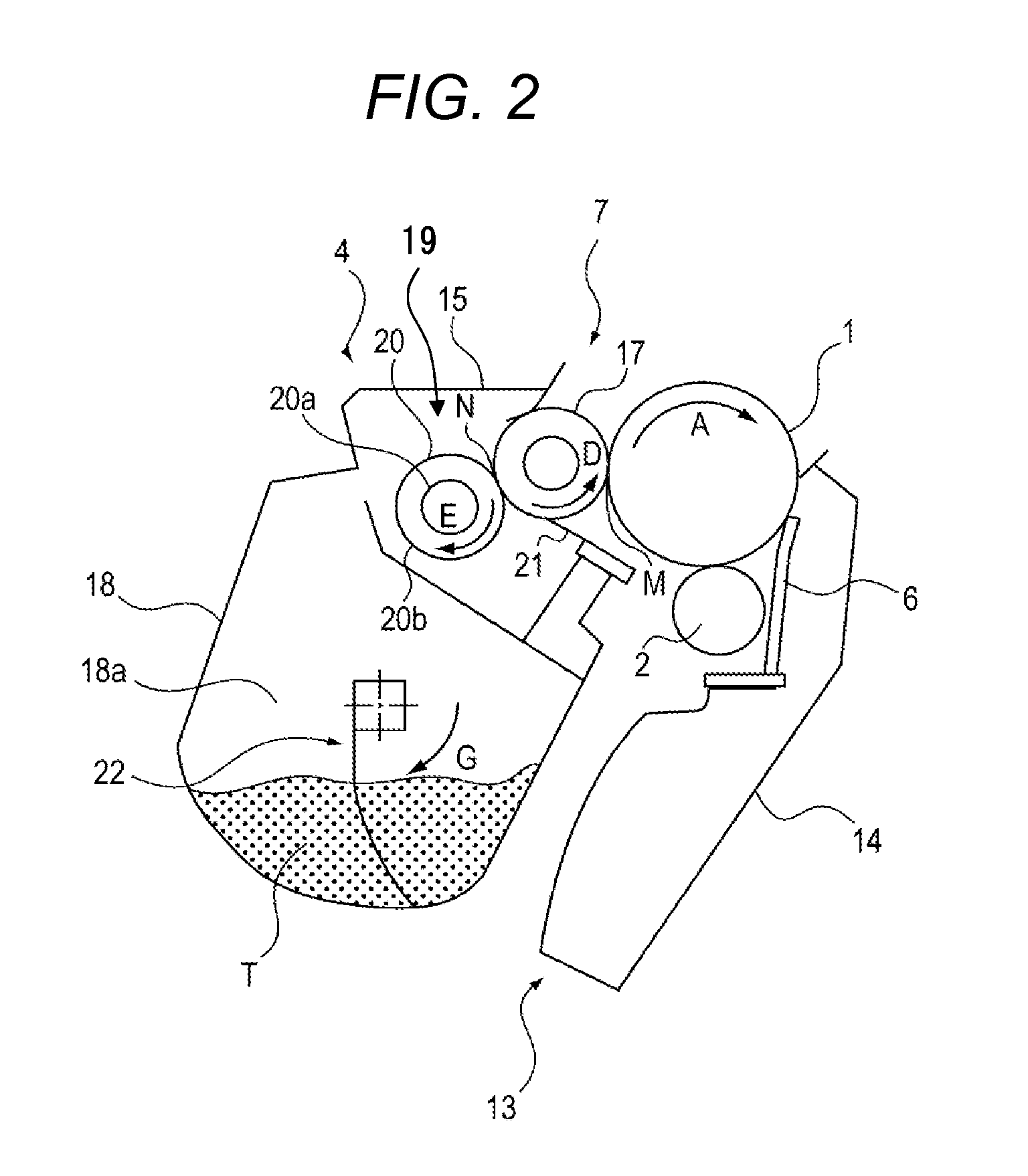
[0026]A first embodiment of the present invention will be described with reference to FIGS. 1 to 6.
[0027](Image Forming Apparatus)
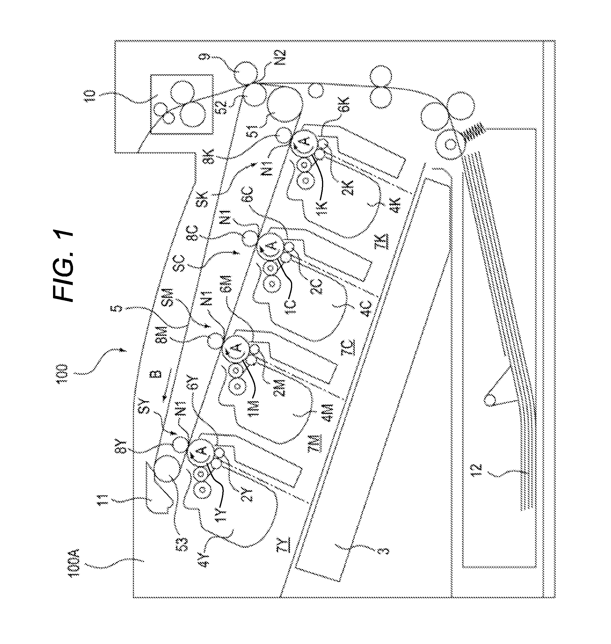
[0028]First, with reference to FIG. 1, an overall structure of an electrophotographic image forming apparatus (image forming apparatus) will be described. FIG. 1 is a schematic sectional view of an image forming apparatus 100 according to the embodiment. The image forming apparatus 100 according to the embodiment is a full-color laser printer of an in-line type and an intermediate transfer type.
[0029]The image forming apparatus 100 is configured to form a full-color image onto a recording material (such as recording sheet, plastic sheet, and cloth) based on image information. The image information is input to an image forming apparatus main body 100A from an image reading apparatus connected to the image forming apparatus main body 100A or from a host apparatus such as a personal computer communicably connected to the image forming apparatus main body 100...
second embodiment
[0093]A second embodiment of the present invention will be described. Both a developing device and an image forming apparatus according to the second embodiment are the same as those described in the first embodiment.
[0094]In the embodiment, a predetermined voltage (developer feed bias) is applied from a bias power source (not shown) not only to the developing roller 17 but also to the toner feed roller 20. With this, toner can be stably fed to the developing roller 17. Further, the toner used in the embodiment is negatively chargeable, and hence, while the developing bias Vdc of −300 V is applied to the developing roller 17, a voltage Vrs of −500 V is applied to the toner feed roller 20 so that a negative electric field is generated in a toner feeding direction.
[0095]FIG. 7 is a timing chart. At the time TO, the photosensitive drum 1 starts to be driven and rotated, and simultaneously, a predetermined charging bias is applied to the charging roller 2. At the time T1, the developing...
PUM
 Abstract
Description
Claims
Application Information
 - R&D
- Intellectual Property
- Life Sciences
- Materials
- Tech Scout
- Unparalleled Data Quality
- Higher Quality Content
- 60% Fewer Hallucinations
Browse by: Latest US Patents, China's latest patents, Technical Efficacy Thesaurus, Application Domain, Technology Topic, Popular Technical Reports.
© 2025 PatSnap. All rights reserved.Legal|Privacy policy|Modern Slavery Act Transparency Statement|Sitemap|About US| Contact US: help@patsnap.com


