Computer, control method of computer, and recording medium

a control method and computer technology, applied in the direction of program control, memory address/allocation/relocation, instruments, etc., can solve the problems of difficult for a programmer to fully understand all of memory securing and releasing processes, inconvenient program execution, etc., to improve the convenience of memory management of the computer system, the effect of efficiently grasping the life of an obj

Inactive Publication Date: 2013-10-31
HITACHI LTD
View PDF0 Cites 14 Cited by
  • Summary
  • Abstract
  • Description
  • Claims
  • Application Information

AI Technical Summary

Benefits of technology

[0019]According to the present invention, it is possible to achieve an effect of efficiently grasping a life of an object without manual works, and of improving convenience of memory management of a computer system using the grasped life of an object.

Problems solved by technology

In developing a computer program, it is known that securing and releasing processes of a memory region used by a program is likely to cause inconvenience to the program such as referring to an incorrect region.
Particularly, in developing a large scale program, it is difficult for a programmer to completely understand all of memory securing and releasing processes.

Method used


Image

  • Computer, control method of computer, and recording medium
  • Computer, control method of computer, and recording medium
  • Computer, control method of computer, and recording medium

Examples


first embodiment

Modified Example of First Embodiment

[0084]In the above-described first embodiment, in a case where information at a generation point of an object generated by the program execution unit 12 has already been registered in the generation point table 24 and the object generation table 23, the information is configured not to be registered (refer to FIG. 6: S182). This configuration has an effect of reducing an analysis process time since a life of an object generated at the same generation point is analyzed only once by the object life analysis unit 19.

[0085]Here, it is considered that there are cases where even objects generated at the same generation point have different lives depending on load circumstances of the computer system 100. In these cases, it is considered that the objects generated at the same generation point are also registered in the object generation table 23 or the like, and life analysis of the objects is performed. Hereinafter, as a modified example of the first em...

second embodiment

[0093]Next, the second embodiment of the present invention will be described. In the first embodiment and the modified example thereof, the pseudo-elapsed time 22 is updated using GC occurrence of the garbage collector 13 as a trigger. In contrast, the second embodiment has one of features in which an update trigger of the pseudo-elapsed time 22 is timing when an object disposition unit 14B secures a region with a specific size for securing an object from the Java heap 21.

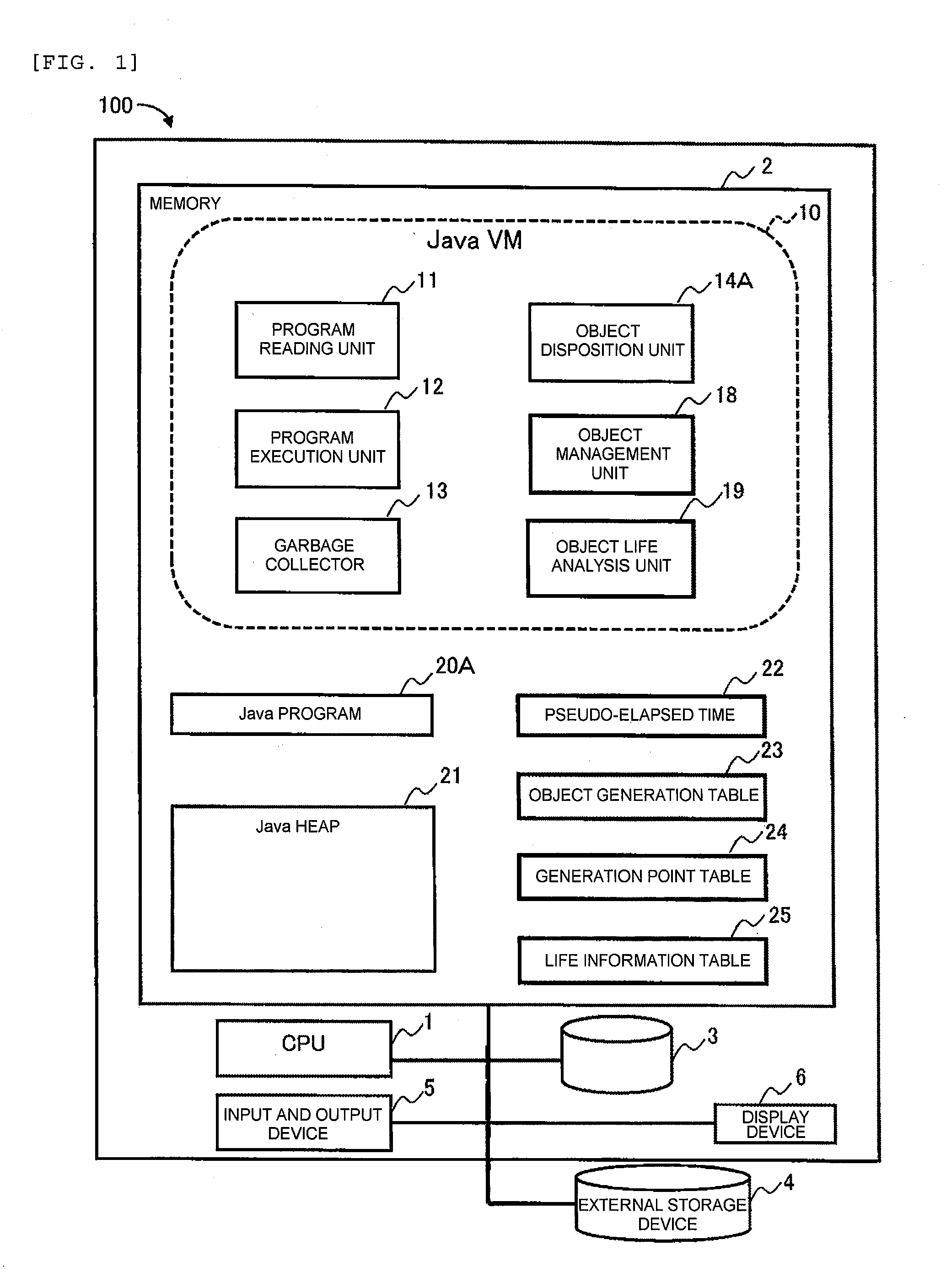
[0094]FIG. 13 shows a configuration of a computer system 200 which is the second embodiment to which the present invention is applied. The computer system 200 has a configuration in which a function of the object disposition unit 14B is different from that of the object disposition unit 14A of the first embodiment, and region securing information 26 is further provided. In addition, in the second embodiment, a particular description will be made of a case where the Java heap 21 has a short life region 211 in which ...

third embodiment

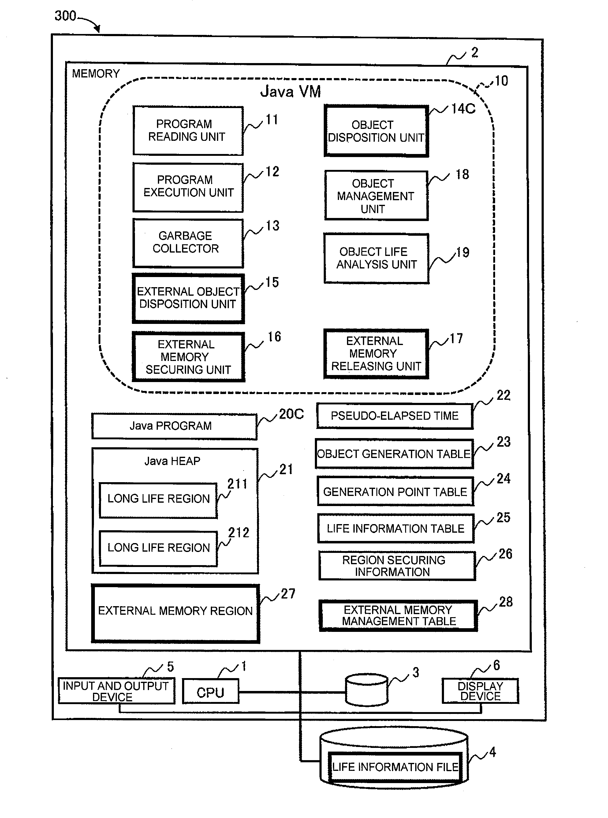
[0112]Next, a computer system 300 which is the third embodiment to which the present invention is applied will be described.

[0113]FIG. 16 shows a configuration of the computer system 300. The computer system 300 substantially has a configuration common to the configuration of the computer systems 100 and 200 of the first and second embodiments, and, further has a memory region (hereinafter, referred to as an “external memory region”) which is not a management target of GC as one feature of the configuration thereof. A Java machine such as the Java VM 10 typically has the Java heap 21 as a memory region storing an object. As described above, the Java heap 21 is a memory region which is a management target of GC by the garbage collector 13. In contrast, an external memory 25 is a memory region which is not a management target of GC by the garbage collector 13.

[0114]The computer system 300 performs a process whether a disposition destination is set to an external memory region 27 or th...


PUM


Abstract

A computer includes a storage region in which an object generated by executing a program is disposed, and a control unit that performs execution of the program and releasing of the storage region. The control unit updates time information using garbage collection, a capacity of objects in a memory, or similar as a trigger, acquires information of a program generating an object and time information at the time of generation of the object which are recorded in a recording device so as to be correlated with each other when the object is generated. The control unit further detects an object which is unnecessary to execute a subsequent program and acquires the time information, and records a difference between the time information at the time of the generation and at the time of the detection in the recording device so as to be correlated with the information of the program.

Description

[0001]The present application is the U.S. National Phase of International Application No. PCT / JP2011 / 006557, filed Nov. 25, 2011, which claims the benefit of Japanese Patent Application No. 2010-268951, filed on Dec. 2, 2010, the entire contents of which are hereby incorporated by reference.TECHNICAL FIELD[0002]The present invention relates to a computer which performs memory management of the computer, a control method of the computer, and a recording medium.BACKGROUND ART[0003]In developing a computer program, it is known that securing and releasing processes of a memory region used by a program is likely to cause inconvenience to the program such as referring to an incorrect region. Particularly, in developing a large scale program, it is difficult for a programmer to completely understand all of memory securing and releasing processes.[0004]As means for solving this, NPL 1 discloses a garbage collector which automatically performs memory management in a program. The garbage coll...

Claims


Application Information

Patent Timeline
Patent Type & Authority Applications(United States)
IPC IPC(8): G06F12/02
CPCG06F12/0253G06F9/45504G06F11/0754G06F12/0276G06F16/16G06F2212/1016
Inventor ADACHI, MASAHIKONISHIYAMA, HIROYASUOBATA, MOTOKI
Owner HITACHI LTD
Why Eureka
Try Eureka