

Method of cutting strengthened glass plate
a technology of strengthened glass and cutting lines, applied in glass tempering apparatus, manufacturing tools, transportation and packaging, etc., can solve the problems of crack formation, thin glass used for mobile devices, and the thinness of mobile devices, so as to improve the accuracy of cutting lines
- Summary
- Abstract
- Description
- Claims
- Application Information
AI Technical Summary
Benefits of technology
Problems solved by technology
Method used
Image

Examples
first embodiment
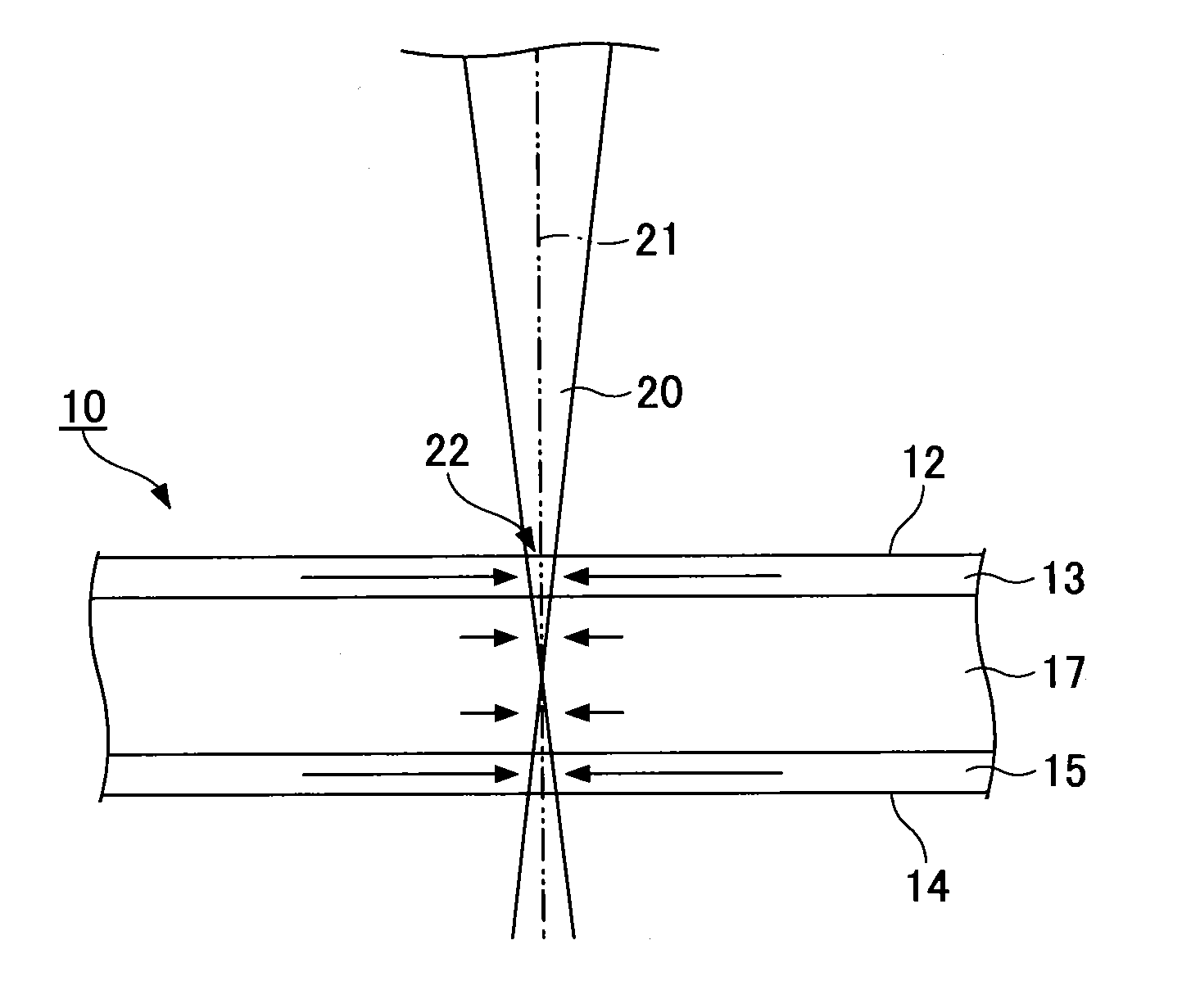
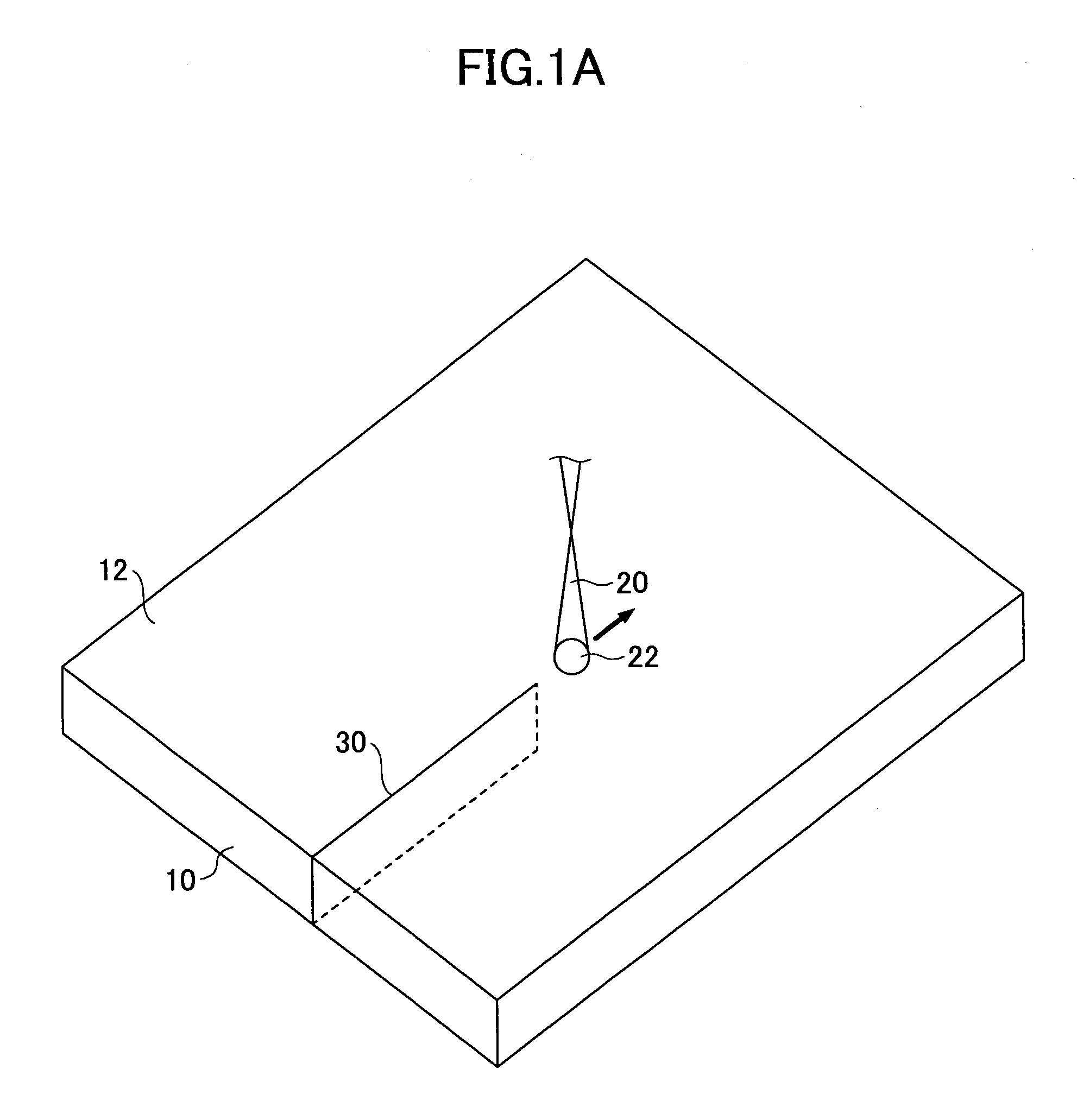
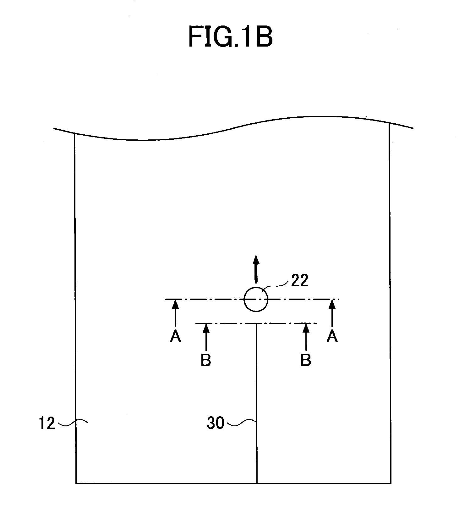
[0038]FIG. 1A and FIG. 1B are views for explaining a method of cutting a strengthened glass plate of a first embodiment. FIG. 1B is a plan view of FIG. 1A. As shown in FIG. 1A and FIG. 1B, a strengthened glass plate 10 is cut by irradiating a laser beam 20 on a front surface (one of main surfaces) 12 of the strengthened glass plate 10 while moving an irradiation area 22 of the laser beam 20 on the front surface 12 of the strengthened glass plate 10 to apply stress on the strengthened glass plate 10.
[0039]The strengthened glass plate 10 is manufactured by a thermally strengthening (or strengthening) method, a chemical strengthening (or strengthening) method or the like, for example. The kind of the strengthened glass is selected in accordance with its usage. For example, a soda lime glass is used as the strengthened glass for a vehicle window glass, a structural window glass, a glass substrate for PDP or a cover glass. Further, a non-alkali glass that does not substantially include a...
second embodiment
[0085]FIG. 9 is a view for explaining a method of cutting a strengthened glass plate of a second embodiment. In FIG. 9, the same components are given the same reference numerals as those in FIG. 1A and explanations are not repeated.
[0086]In this embodiment, similar to the first embodiment, the strengthened glass plate 10 is cut by irradiating the laser beam 20 on the front surface 12 of the strengthened glass plate 10 while moving the irradiation area 22 of the laser beam 20 on the front surface 12 of the strengthened glass plate 10.
[0087]Further, in this embodiment, the strengthened glass plate 10 is cut using a propagation of a crack by the remaining tensile stress of the intermediate layer 17 by having the strengthened glass plate 10 and the laser beam 20 satisfy an equation 010 with respect to the laser beam 20 is α (cm−1) and the thickness of the strengthened glass plate 10 is t (cm). It means that it is possible to control the propagation of the crack 30 generated in the stren...
third embodiment
[0091]FIG. 10A and FIG. 10B are views for explaining a method of cutting a strengthened glass plate of a third embodiment. FIG. 10A is a cross-sectional view illustrating a cross-section of a strengthened glass plate, FIG. 10B is a plan view illustrating the front surface of the strengthened glass plate in an enlarged manner. In FIG. 10A, a direction of an arrow indicates a direction of a flow of gas. In FIG. 10A and FIG. 10B, the same components are given the same reference numerals as those in FIG. 1A, FIG. 9 or the like and explanations are not repeated.
[0092]There is a difference between the present embodiment and the second embodiment that the irradiation area 22 of the laser beam 20 is positioned inside the outer edge of the spraying area 42 in this embodiment, where the spraying area 42 of the gas 40 is provided in the vicinity of the back side of the irradiation area 22 of the laser beam 20 in the second embodiment. Other structures are the same as those of the second embodi...
PUM
| Property | Measurement | Unit |
|---|---|---|
| Thickness | aaaaa | aaaaa |
| Thickness | aaaaa | aaaaa |
| Thickness | aaaaa | aaaaa |
Abstract
Description
Claims
Application Information