Sensor

a technology of a sensor and a fluid, applied in the direction of converting sensor output, measurement devices, instruments, etc., can solve the problem of false measurement signal, and achieve the effect of durable adhesive bond, cost-effective production, and easy stamping

Active Publication Date: 2013-11-07
MARQUARDT GMBH SCHLOSSTRASSE 16 7201 RIETHEIM-WEILHEIM 1 WEST GERMANY
View PDF4 Cites 9 Cited by
  • Summary
  • Abstract
  • Description
  • Claims
  • Application Information

AI Technical Summary

Benefits of technology

[0005]The object of the present invention is to develop the measuring apparatus in such a way that the quality of the measuring signal is improved. In particular, a stable mechanical measuring system is to be created, which functions independently of external influences where possible.
[0006]In the case of the measuring apparatus according to the present invention, the resilient element is held on the housing and / or is fastened on the housing at the edge of the resilient element, more specifically at parts of the edge. The suspension or the fastening of the resilient element is thus decoupled from the actual spring element, such that the spring element can swing freely. Due to the decoupling, disturbing external influences cannot act on the spring element, thus advantageously preventing falsifications of the measuring signal. In other words, the present invention provides a mechanical decoupling of the outer contours of the measuring apparatus from the actual mechanical measuring system by means of a sprung suspension.
[0007]In one embodiment, to reduce the installation height of the measuring apparatus, it is proposed for the resilient element to be formed in the manner of a disk-shaped leaf spring. The leaf spring expediently has a substantially circular shape, which corresponds substantially to the shape of the diaphragm. A particularly high restoring force can be achieved with the resilient element since the leaf spring has a spring element running in a spiraled manner from the center to the edge region of the leaf spring. A compact embodiment with high spring force is thus ensured.

Problems solved by technology

It has been proven that external influences on the measuring apparatus disturb the resilient element, which in turn may lead to a falsification of the measuring signal.

Method used


Image

  • Sensor
  • Sensor
  • Sensor

Examples


Embodiment Construction

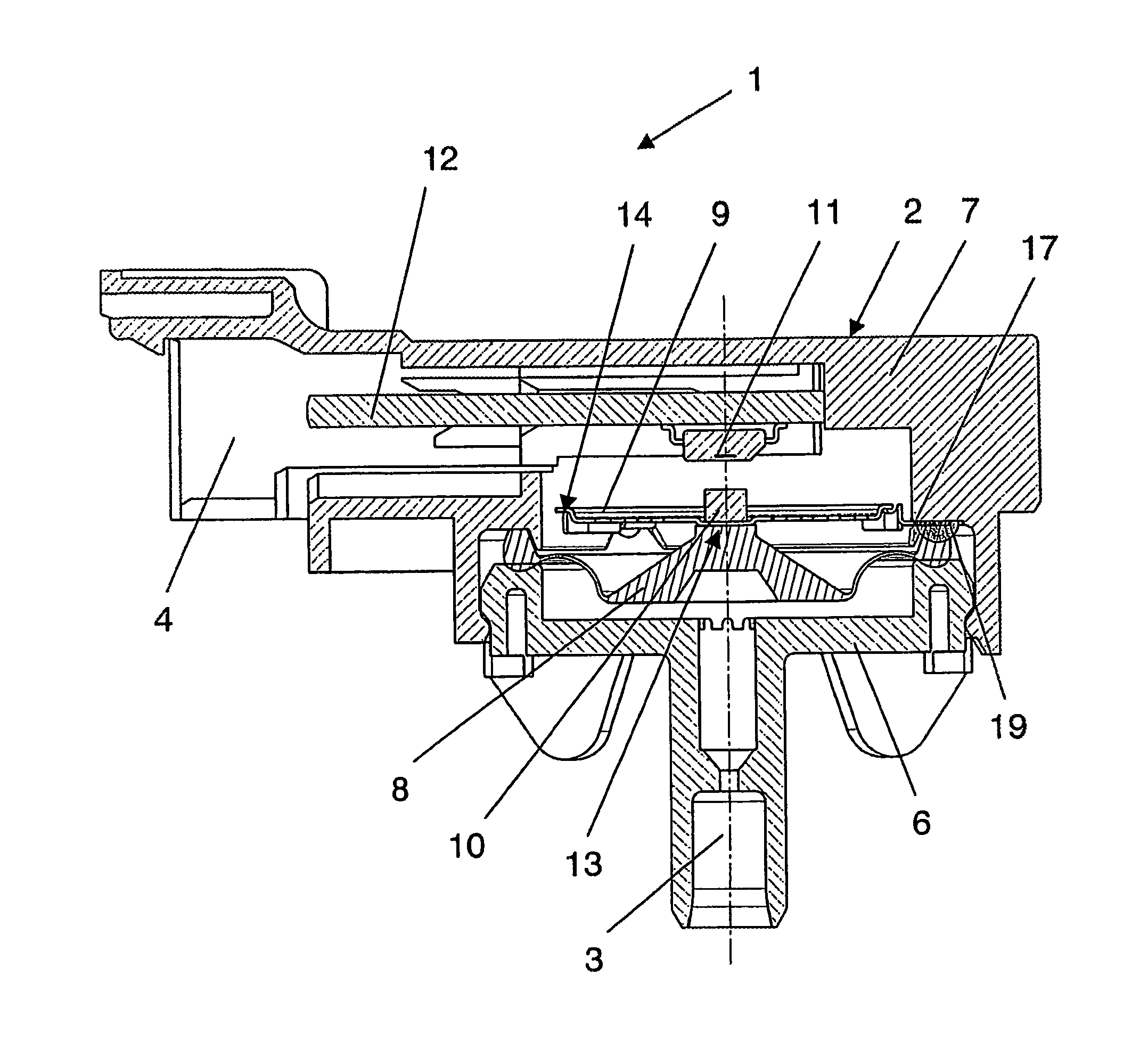
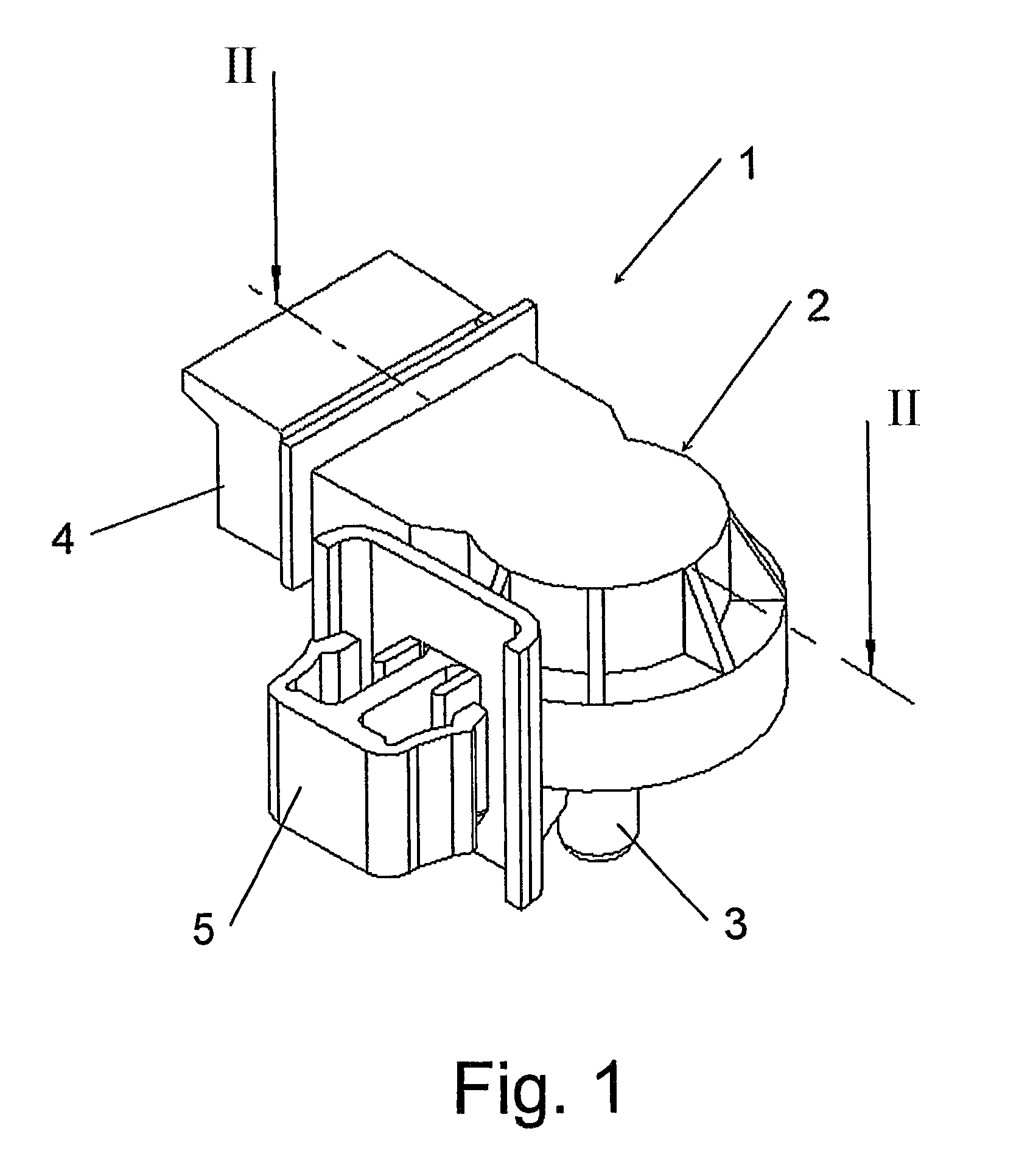
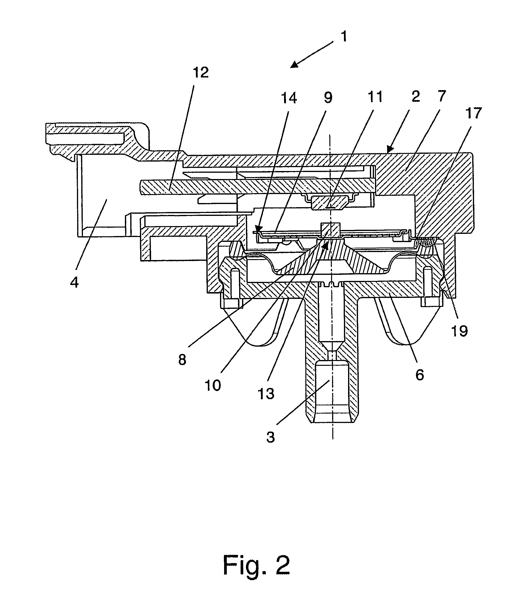
[0020]In FIG. 1, a pressure sensor 1 can be seen that is used as a measuring apparatus for measuring a measurement variable of a fluid, more specifically in the present case for measuring the pressure of a liquid in a domestic appliance. The pressure sensor 1 has a housing 2, on which a connection piece 3 is arranged for feeding the liquid that is to be measured, and also a plug connection 4 for connection of the electrical feed lines. The pressure sensor 1 can be assembled in the domestic appliance by means of a detent mechanism 5 located on the housing 2. The housing 2 lastly comprises a base 6 and a cover 7 according to FIG. 2.

[0021]As can also be deduced from FIG. 2, a diaphragm 8 is arranged in and / or on the housing 2 and the liquid acts on the diaphragm via the connection piece 3. The diaphragm 8 is deflected in accordance with the pressure prevailing in the liquid. A resilient element 9 located in the housing 2 acts as a spring on the diaphragm 8 in order to restore the diaph...


PUM

PropertyMeasurementUnit
pressuresaaaaaaaaaa
adhesive bondingaaaaaaaaaa
resilientaaaaaaaaaa

Abstract

The invention relates to a measuring apparatus for measuring a measurement variable of a fluid, particularly a sensor, such as a pressure sensor or a displacement sensor. The measuring apparatus comprises a housing, a diaphragm arranged in and / or on the housing, and a resilient element formed in the manner of a leaf spring for restoring the diaphragm. A signal transmitter is operatively connected to the diaphragm and / or the resilient element, and a signal receiver cooperates with the signal transmitter. The resilient element is fastened on the housing at the edge of the resilient element, more specifically in particular only at parts of the edge.

Description

CROSS REFERENCE TO RELATED APPLICATIONS[0001]This application is a continuation of International Application No. PCT / EP2011 / 005975 filed Nov. 29, 2011, which designated the United States, and claims the benefit under 35 USC §119(a)-(d) of German Application No. 10 2010 053 455.2 filed Nov. 29, 2010, the entireties of which are incorporated herein by reference.FIELD OF THE INVENTION[0002]The invention relates to an apparatus for measuring a measurement variable of a fluid, particularly a sensor, such as pressure sensor, a displacement sensor or the like.BACKGROUND OF THE INVENTION[0003]The measuring apparatus may be a sensor, such as a pressure sensor, a displacement sensor, or the like. Such measuring apparatuses are used in particular to measure a measurement variable of a fluid, for example, to measure the water level in washing machines, dishwashers, wet and / or dry vacuum cleaners or in other water-guiding parts of domestic appliances. In particular, these measuring apparatuses a...

Claims


Application Information

Patent Timeline
Patent Type & Authority Applications(United States)
IPC IPC(8): G01L19/00
CPCG01L19/0007G01L9/007G01L19/143G01D5/145G01D11/16G01L19/003
Inventor WEISSER, DIETMARSCHEITER, MARKUS
Owner MARQUARDT GMBH SCHLOSSTRASSE 16 7201 RIETHEIM-WEILHEIM 1 WEST GERMANY
Why Eureka
Try Eureka