Method and magnetic resonance scanner for hyperintense display of areas in the vicinity of dipole fields

Active Publication Date: 2013-03-21
SIEMENS HEALTHCARE GMBH
View PDF10 Cites 5 Cited by
  • Summary
  • Abstract
  • Description
  • Claims
  • Application Information

AI Technical Summary

Benefits of technology

[0013]An object of the present invention is to provide a method, a magnetic resonance scanner, and a non-transitory electronically readable data storage medium that enable a differe

Problems solved by technology

The magnetically active substances, however, induce a dipole field in their vicinity, which disturbs the otherwise ideally homogenous main magnetic field of the magnetic resonance scanner.
This leads to signal losses with gradient echo (GRE) sequences and to distortions (susceptibility artifacts) in spin echo (SE) sequences.
In the vicinity of magnetic impurities, e.g. magnetically active substances, long echo times of this type have the disadvantage that, through dephasing or suscep

Method used


Image

  • Method and magnetic resonance scanner for hyperintense display of areas in the vicinity of dipole fields
  • Method and magnetic resonance scanner for hyperintense display of areas in the vicinity of dipole fields
  • Method and magnetic resonance scanner for hyperintense display of areas in the vicinity of dipole fields

Examples


Example

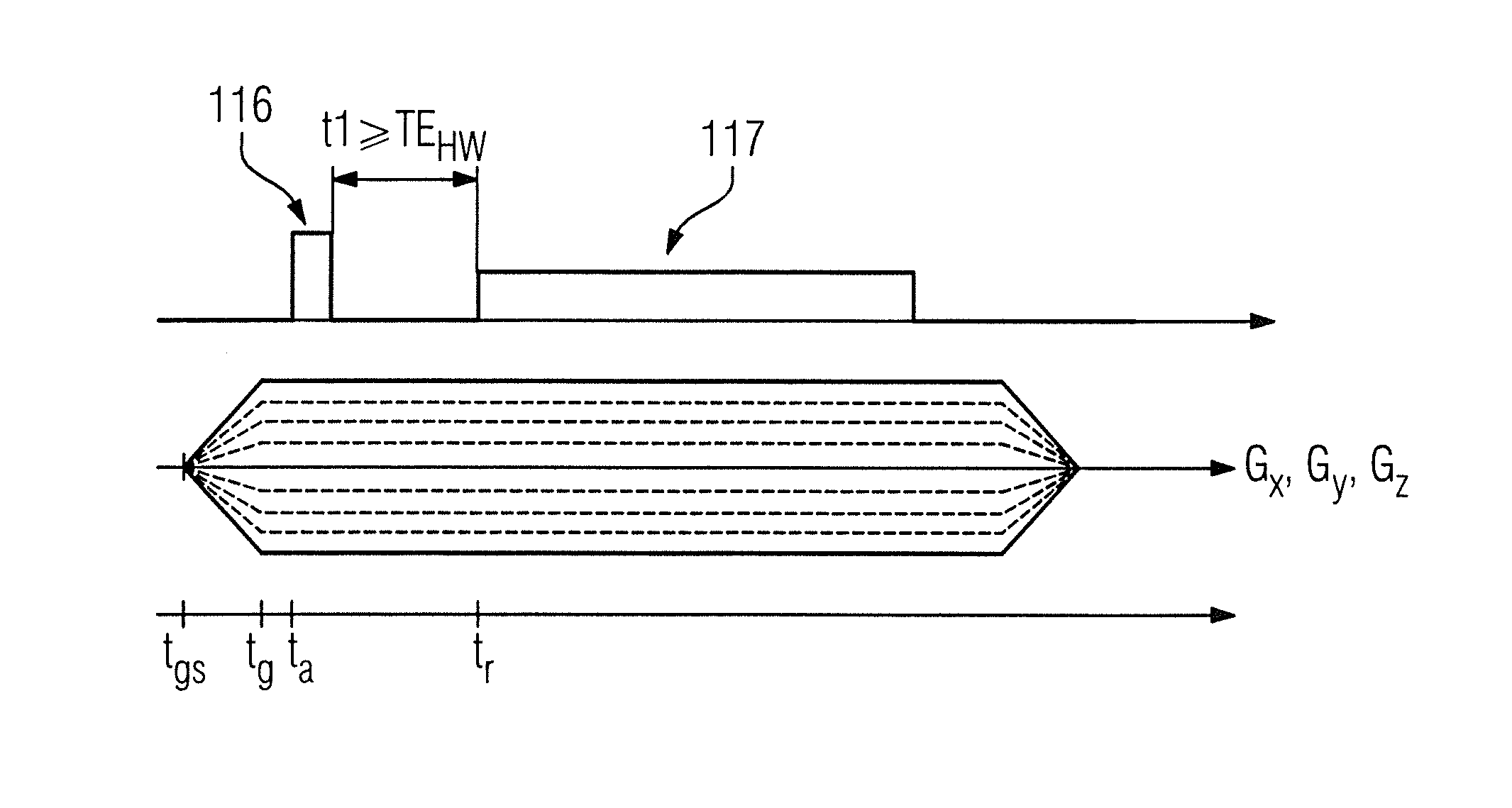
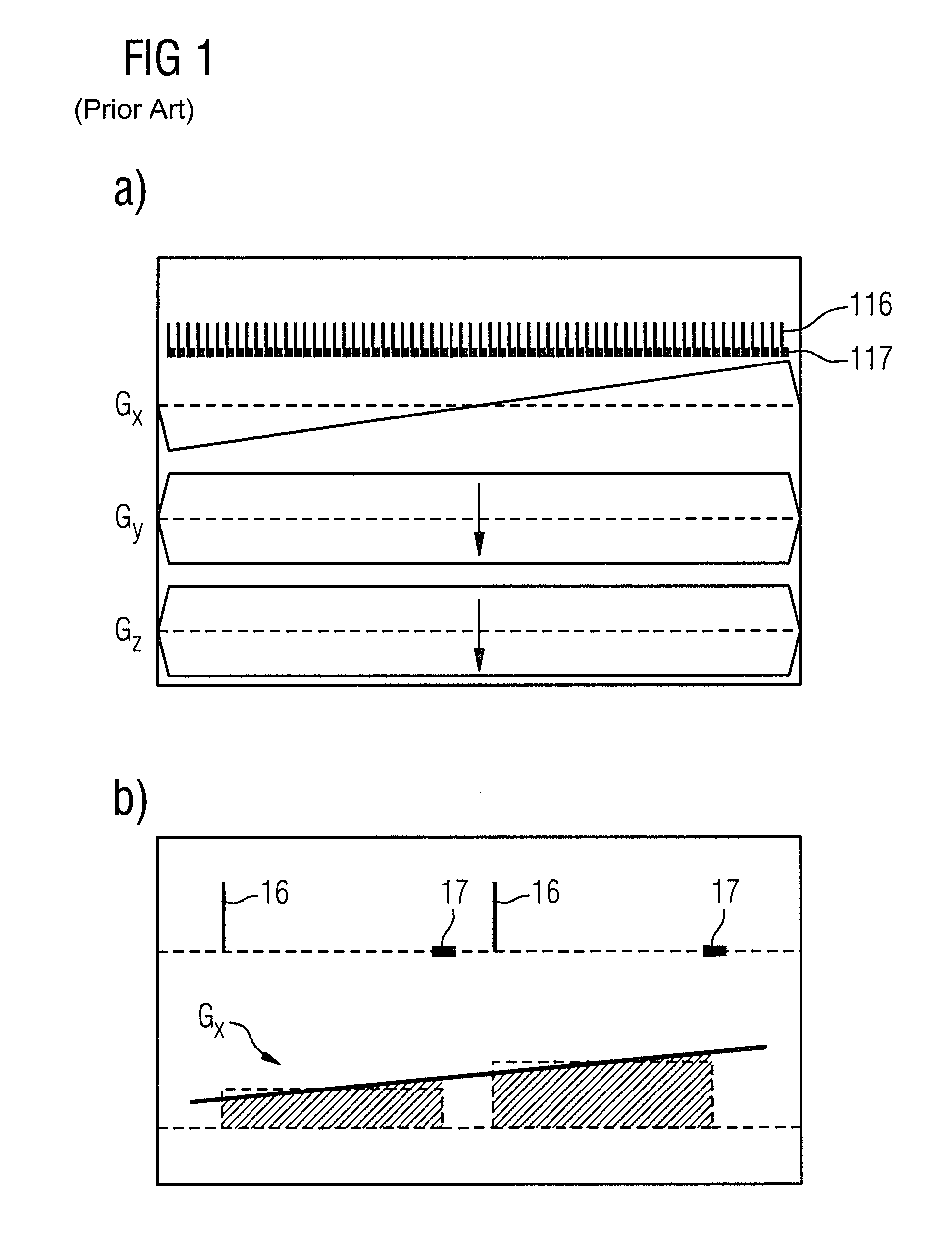
[0035]A sequence for capturing (acquiring data entries for) a line in the k-space is depicted at (a) in FIG. 1. It can be seen that the two phase encoding gradients Gy and Gz are activated with a constant strength, while the strength of the third phase encoding gradient Gx is continuously increased.

[0036]In (b) of FIG. 1, the capturing of two raw data points is depicted in detail. It can be seen that the echo time, i.e. the temporal spacing, is constant from the RF excitation pulse 16 up to the beginning of the scanning timespan 17. In addition, the phase encoding gradient Gx runs in incremental steps from down to up. In doing so, the phase encoding gradient Gx for scanning a raw data point is kept constant, which means that the phase encoding gradient Gx is kept constant for the timespan TE (echo time).

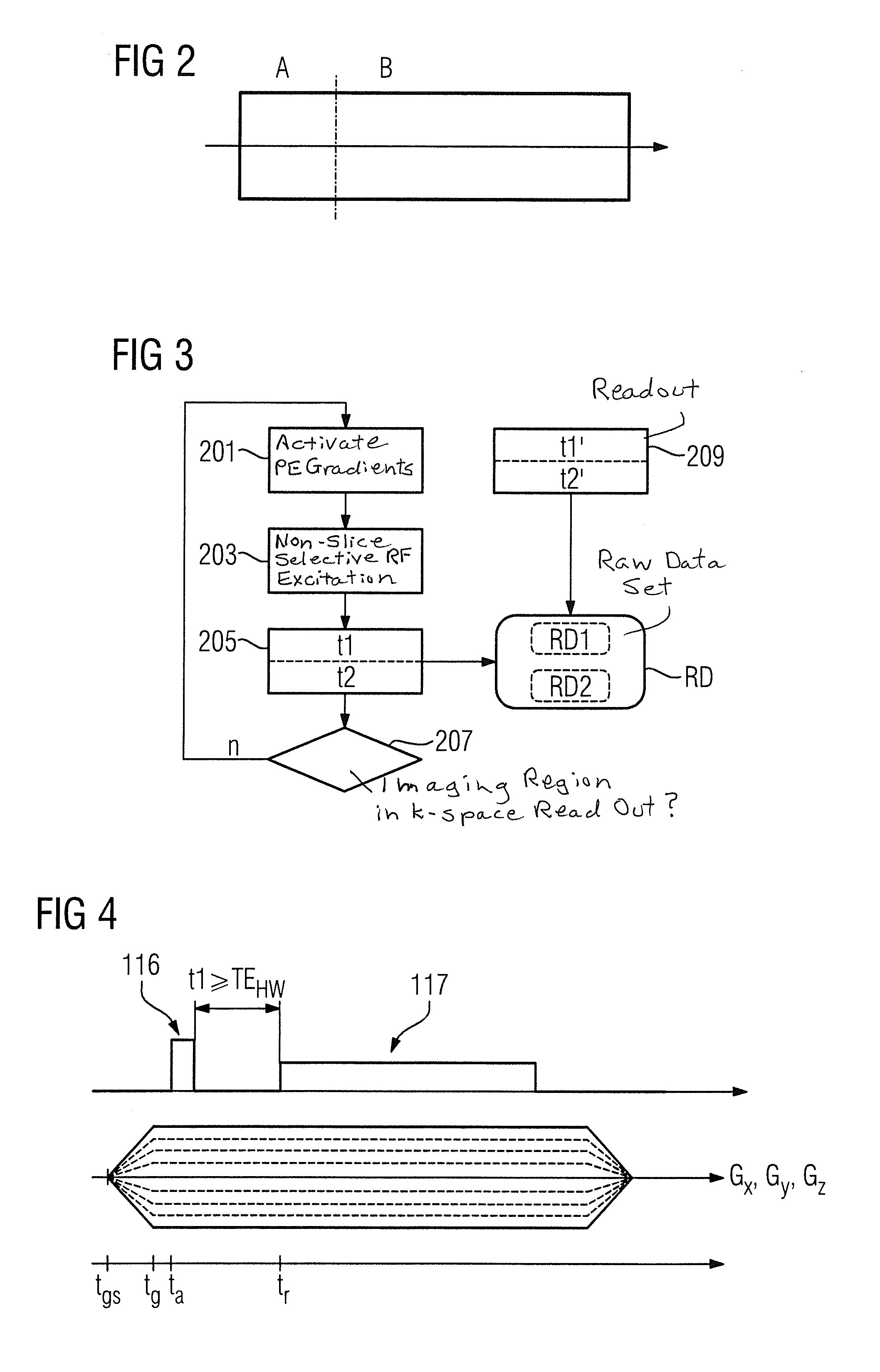
[0037]FIG. 2 depicts, in a schematic manner, how a sequence suitable for the method according to the invention can be subdivided. For each imaged part B, in which the measurement sig...


PUM


Abstract

In a method and magnetic resonance apparatus for the hyperintense display of areas containing particles of magnetically active substances, in an examination region in a measurement volume of a magnetic resonance scanner, measurement data from the examination area are generated by a pulse sequence and recorded, the pulse sequence causing an echo time of less than one millisecond, so that a suppression of undesired signals is also caused.

Description

BACKGROUND OF THE INVENTION[0001]1. Field of the Invention[0002]The present invention relates to a method for the hyperintense display of areas in the vicinity of dipole fields, a magnetic resonance scanner, a computer program and an electronically readable data medium for said program.[0003]2. Description of the Prior Art[0004]The magnetic resonance (MR) technology is a known image modality, with which images of the interior of an object to be examined can be generated. Stated simply, the object to be examined is positioned in a magnetic resonance apparatus in a strong static, homogenous basic magnetic field, also referred to as a B0 field, having field strengths of 0.2 tesla to 7 tesla and higher, such that nuclear spins in the object orient themselves along the basic magnetic field. High frequency excitation pulses (RF pulses) are directed into the object to be examined in order to trigger nuclear magnetic resonances. The triggered resonance signals are measured (detected), and b...

Claims


Application Information

Patent Timeline
IPC IPC(8): G01R33/56G01R33/34
CPCG01R33/56G01R33/34G01R33/5607G01R33/5601G01R33/4816
Inventor GRODZKI, DAVID
Owner SIEMENS HEALTHCARE GMBH
Why Eureka
Try Eureka