
Thin film solar cell structure

a solar cell and thin film technology, applied in the direction of basic electric elements, electrical equipment, semiconductor devices, etc., to achieve the effects of photovoltaic conversion, increased power efficiency, and more power

Inactive Publication Date: 2013-11-07
YANG CHIH HUA
View PDF2 Cites 3 Cited by
  • Summary
  • Abstract
  • Description
  • Claims
  • Application Information

AI Technical Summary

Benefits of technology

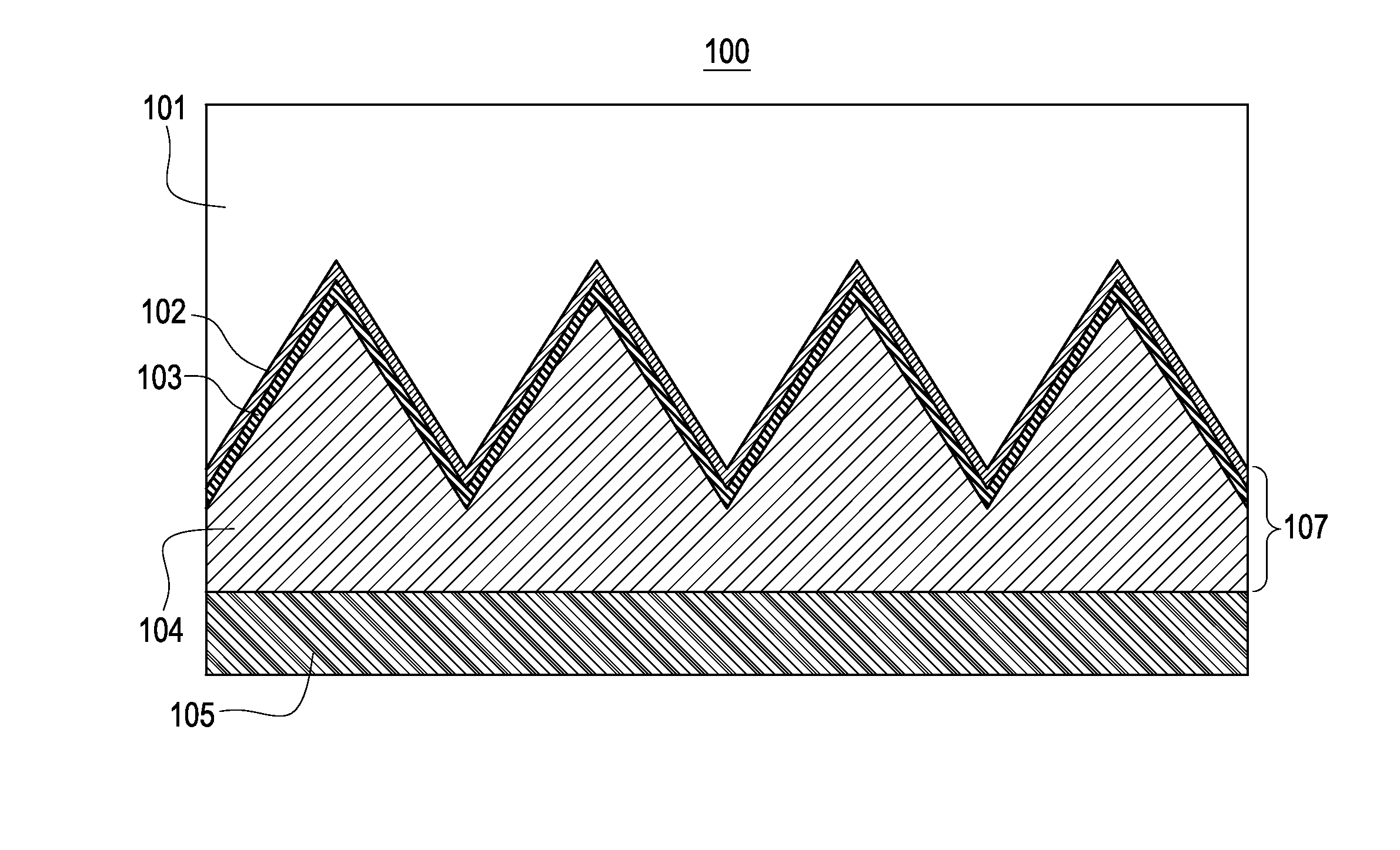
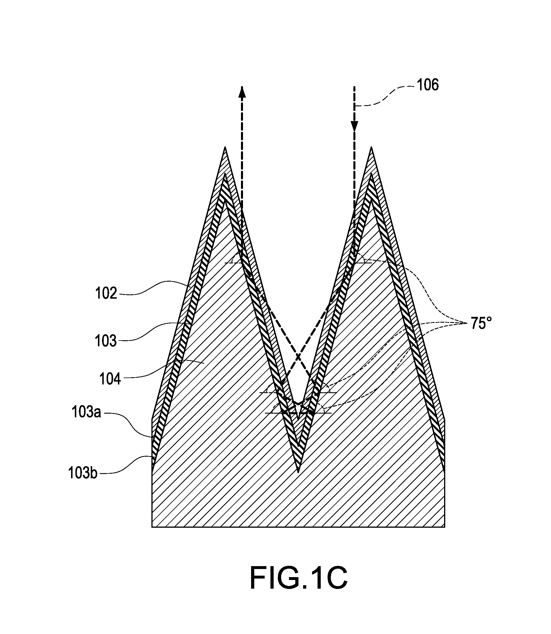
The present invention is about a non-planar thin film photovoltaic conversion structure that increases the efficiency of photovoltaic conversion. This is achieved by causing several reflections for almost every single vertically incident photon. The invention has two main differences from prior art: the vertical distance between the peak and the valley of the light absorption layer is at least larger than or equal to its thickness, and the slope of the non-planar light absorption is larger. These features help to minimize reflection loss and increase the amount of light that goes through the structure without directly leaving the cell.

Problems solved by technology

1. The vertical distance between the peak and the valley of the light absorption layer is at least larger than or equal to its thickness in the present invention. Therefore, almost every photon of the incident sunlight which is not absorbed by the light absorption layer will be reflected by the second conductive layer and go through the light absorption layer and proceed photovoltaic conversion again. The rest photons will go somewhere else at the solar cell and proceed photovoltaic conversion again. Same procedure will repeat again and again till the light leave the non-planar thin film solar cell. While the vertical distance between the peak and the valley of the texture in the prior art mentioned above is smaller than the thickness of the light absorption layer. The purpose of the texture with small dimension is to scatter the incident sunlight or the reflected light and increase the possibility for the light going back and forth in the photovoltaic conversion structure. But there still is some of the light leaves the photovoltaic conversion structure directly or after only one or two reflections.
2. The slope of the non-planar light absorption in the present invention is larger. All solar cells with a non-planar surface suffer from the increasing reflection loss at the interface between the first conductive layer and the light absorption layer. With a larger slope, the reflected light related to reflection loss in the present invention does not leave the solar cell directly as in the prior art but go somewhere else of the solar cell and proceed photovoltaic conversion again. If the reflection loss shows up again at the “somewhere”, same procedure as mentioned above will be proceeded again till the light leave the solar cell. However, the reflection loss is minimized at last with several times of the reuse of the reflection losses.

Method used


Image

  • Thin film solar cell structure
  • Thin film solar cell structure
  • Thin film solar cell structure

Examples


Embodiment Construction

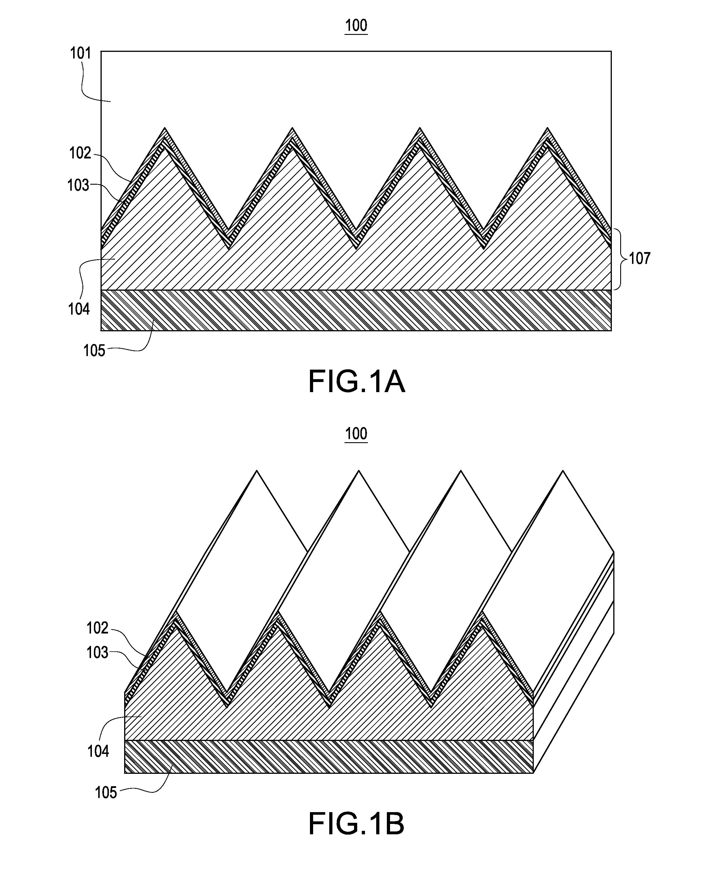
[0019]FIG. 1A is a vertical cross-sectional view of an embodiment of the present invention which can be applied in a thin film solar cell, for example, silicon type solar cell, compound type solar cell and dye-sensitized solar cell . . . etc. The incident sunlight is reflected for several times (namely, has multiple reflections) to increase the power conversion efficiency in the photovoltaic conversion structure of thin film solar cell structure 100. Thin film solar cell structure 100 comprises a photovoltaic conversion structure 107 and an optional protection layer 101 and an optional substrate 105. Photovoltaic conversion structure 107 is a stack of an at least one layer of non-planar light absorption layer 103, a light transmissive first conductive layer 102(For example, ITO or AZO) and an at least partially transparent or completely reflective second conductive layer 104. FIG. 1B shows a perspective view of the embodiment shown in FIG. 1A, where the optional protection layer 101...


PUM


Abstract

A thin film solar cell includes a protection layer, a substrate and a photovoltaic conversion structure having a stack of one or several of non-planar light absorption layers, a first conductive layer being light transmissive and a second conductive layer being at least partially transparent or totally reflective. When the second conductive layer is totally reflective, it reflects the sunlight to the adjacent part of the thin film solar cell, proceeding another photovoltaic conversion and generating electric power again. If the non-planar light absorption layer is sloped enough, there will be several photovoltaic conversions produced by the same incident sunlight. More power will be generated and the efficiency of conversion is increased. If the second conductive layer is at least partially transparent, the incident light will be reflected less. However, the structure will provide several opportunities of photovoltaic conversions for the light with larger incident angle.

Description

BACKGROUND OF THE INVENTION[0001]1. Field of the Invention[0002]The present invention relates to a thin film solar cell structure which causes two or more reflections for an vertically incident sunlight and thus more photovoltaic conversions are produced by every single vertically incident light. More electric power is therefore generated and the photovoltaic conversion efficiency is improved.[0003]2. Description of Related Art[0004]Solar cell is a device which converts solar power to electric power. It can be categorized, in material, to silicon type, compound type and organic type. It can also be categorized to bulk type and thin film type in other way. Take silicon type solar cell as an example, usually single-crystalline silicon solar cells and poly-crystalline silicon solar cells belong to bulk type while amorphous silicon solar cells and micro-crystalline solar cells silicon belong to thin film type.[0005]The light absorption layer, the first conductive layer and the second co...

Claims


Application Information

Patent Timeline
Patent Type & Authority Applications(United States)
IPC IPC(8): H01L31/0352
CPCH01L31/02366H01L31/03529H01L31/056Y02E10/52
Inventor YANG, CHIH-HUA
Owner YANG CHIH HUA
Learn More