
Buffering stop structure and corresponding packing case

Active Publication Date: 2013-11-07
TCL CHINA STAR OPTOELECTRONICS TECH CO LTD
View PDF0 Cites 8 Cited by
  • Summary
  • Abstract
  • Description
  • Claims
  • Application Information

AI Technical Summary

Benefits of technology

The present invention provides a buffering stop structure and a corresponding packing case. The manufacture cost of the packing case is lower, and the buffering effect is better, which solves the problems of existing technology that has higher manufacture cost and may cause environment pollution. In summary, the technical effects of the present invention are improved manufacture cost and better buffering effect.

Problems solved by technology

With the rapid advancement and development of liquid crystal display technology, a traditional cathode ray tube (CRT) is gradually weeded out because it has problems that it will occupy more space and waste great quantity of energy, so it is replaced by a liquid crystal display (LCD).
However, because the LCD has characters of light-thin and fragile, the requirement of a corresponding packing case is higher.
However, the case main body of EPP has good character of buffering, but its material and the manufacture cost are higher, and the shrinkage rate thereof is larger, so that it is difficult to control the size; and the case main body of EPO is difficult to be decomposed, so it may be causes a problem of environment pollution.

Method used


Image

  • Buffering stop structure and corresponding packing case
  • Buffering stop structure and corresponding packing case
  • Buffering stop structure and corresponding packing case

Examples


Embodiment Construction

[0043]The description of the preferred embodiments refers to the drawings, so as to illustrate the specific embodiments of the present invention which can be carried out. Furthermore, the directional terms described in the present invention, such as upper, lower, front, rear, left, right, inner, outer, side and etc., are only directions referring to the accompanying drawings, so that the used directional terms are used to describe and understand the present invention, but the present invention is not limited thereto.

[0044]In the drawings, the units with the similar structure use the same numerals.

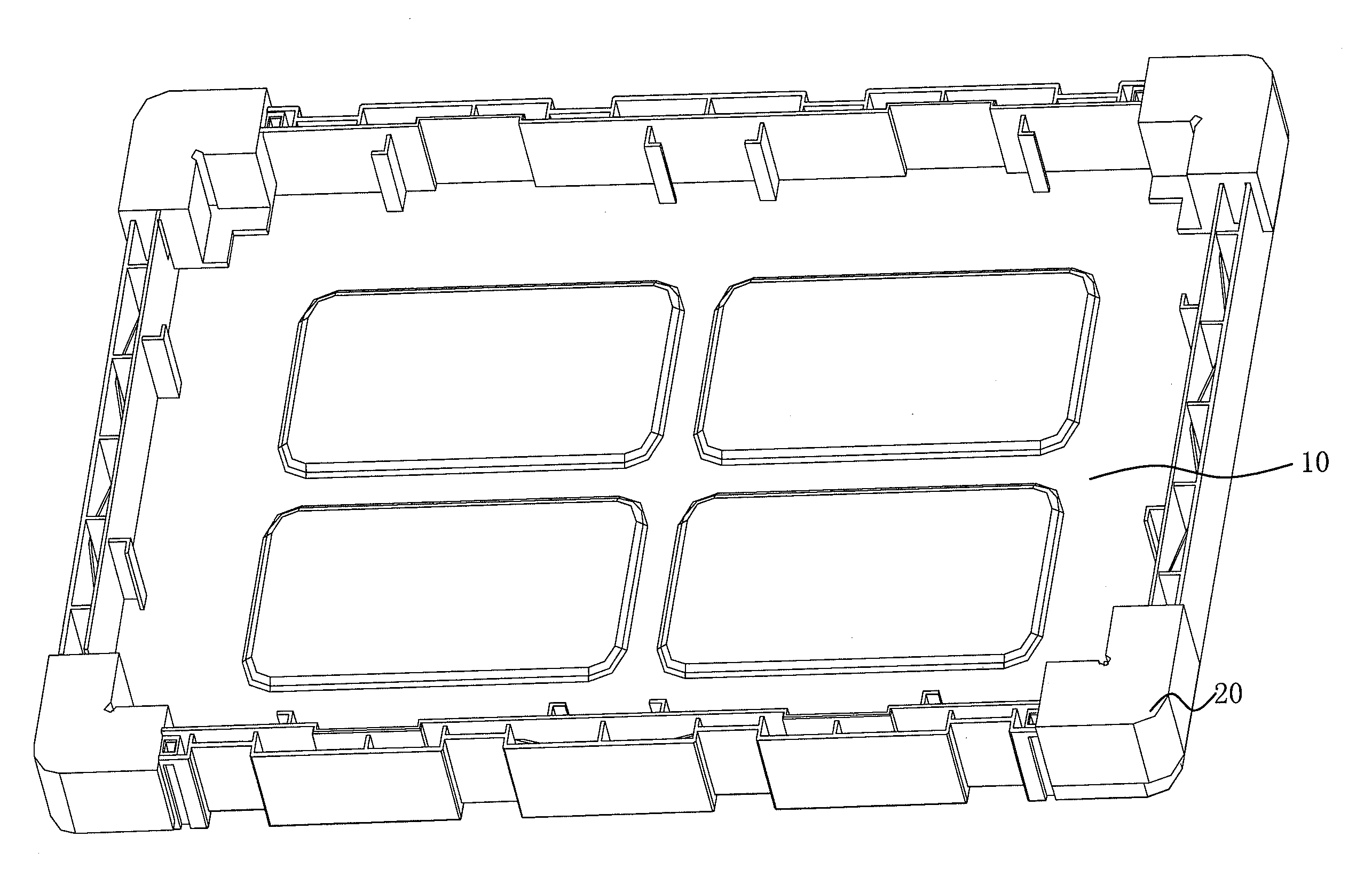
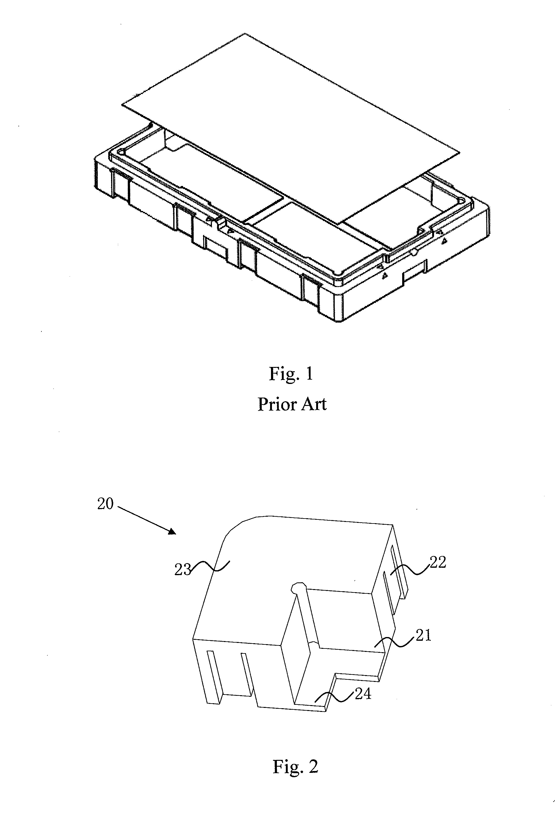
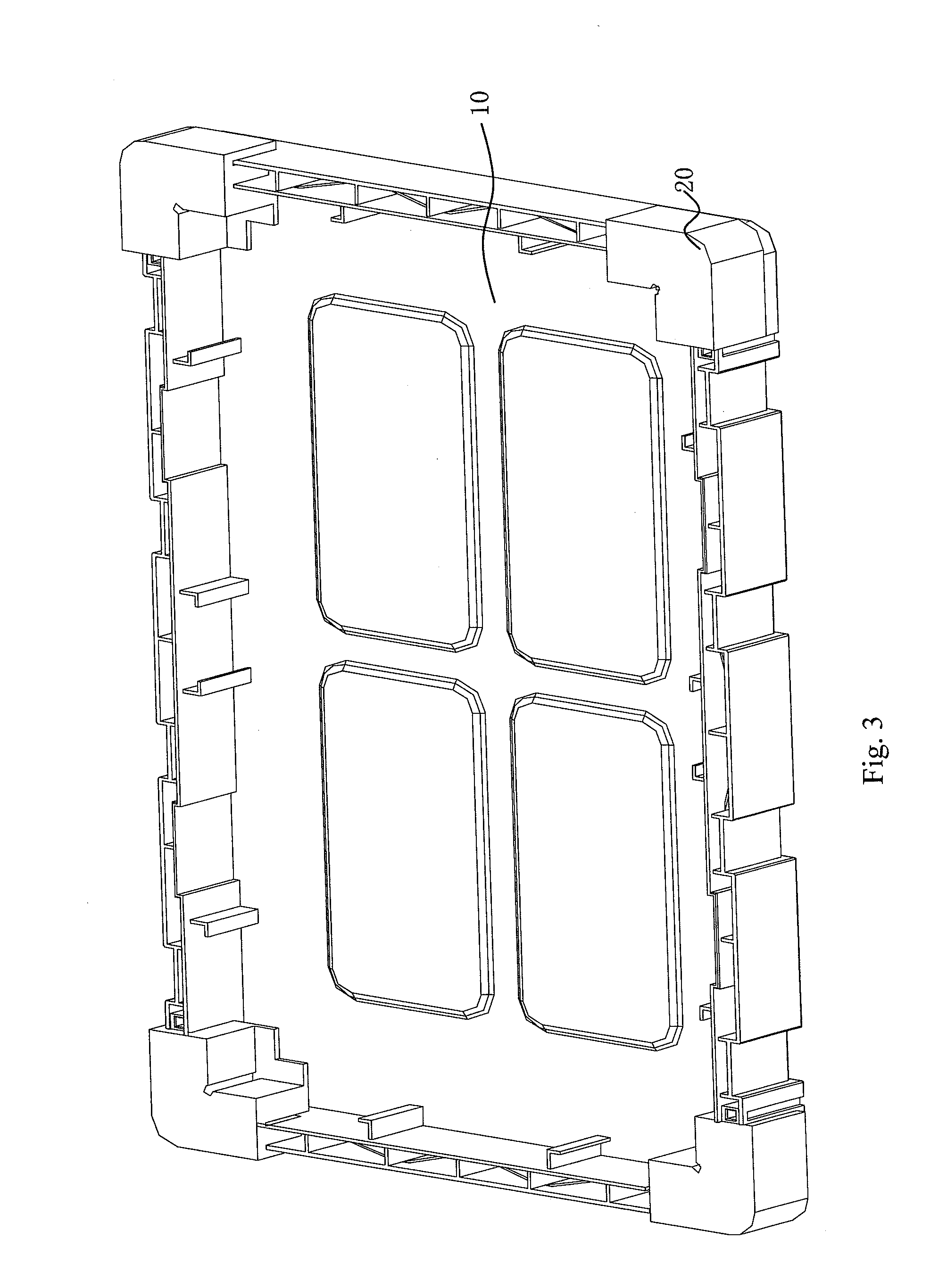
[0045]Referring now to FIGS. 2 and 3, a structural schematic view of a buffering stop structure of a preferred embodiment according to the present invention is illustrated in FIG. 2; and a structural schematic view of a packing case of a preferred embodiment according to the present invention is illustrated in FIG. 3. As shown in these drawings, the packing case comprises a case main body 1...


PUM


Abstract

The present invention relates to a buffering stop structure and a corresponding packing case. The buffering stop structure is disposed at a connecting corner between adjoining side surfaces of a corresponding case main body. The case main body is used to load a liquid crystal display (LCD) panel. The buffering stop structure comprises a fixing portion, a connecting portion and a case buffering portion. The manufacture cost of the buffering stop structure and the corresponding packing case of the present invention is lower, and the buffering effect thereof is better, so as to solve the problems of the packing case of existing technology that has higher manufacture cost and may cause environment pollution.

Description

FIELD OF THE INVENTION[0001]The present invention relates to a field of packing technology, and more particularly to a buffering stop structure and a corresponding packing case which are used for packing a liquid crystal panel.BACKGROUND OF THE INVENTION[0002]With the rapid advancement and development of liquid crystal display technology, a traditional cathode ray tube (CRT) is gradually weeded out because it has problems that it will occupy more space and waste great quantity of energy, so it is replaced by a liquid crystal display (LCD). However, because the LCD has characters of light-thin and fragile, the requirement of a corresponding packing case is higher.[0003]A traditional packing case of the LCD as shown in FIG. 1, a structural schematic view of a packing case of existing technology is illustrated in FIG. 1. The packing case comprises a case main body, wherein fixing structures for fitting the size and shape of the LCD panel are disposed inside the case main body. It furth...

Claims


Application Information

Patent Timeline
IPC IPC(8): G02F1/1333
CPCG02F1/133308G02F2201/503
Inventor CHEN, SHIH-HSIANGKUO, YICHENGCHENG, JIAHEHU, QIAN-SHUANG
Owner TCL CHINA STAR OPTOELECTRONICS TECH CO LTD
Learn More