
Full-automatic detecting system and method for transformer

Active Publication Date: 2013-11-07
STATE GRID ZHEJIANG ELECTRIC POWER
View PDF0 Cites 17 Cited by
  • Summary
  • Abstract
  • Description
  • Claims
  • Application Information

AI Technical Summary

Benefits of technology

The present patent application proposes a system for full-automatic examination of transformers. The system includes a material conveying line for delivering transformers to be examined, an examination conveying line for moving transformers to examination devices, an insulation test device for detecting insulation resistances, an error examining device for detecting basic errors, a Laser marking device for imprinting identification information, a material discharging device for transferring transformers to a storage system, an appearance inspection device for taking photos of transformers and checking their contents, multiple testing device sets for accurate and efficient examination, and a control system for coordinating the operation of the various devices. The system improves efficiency and accuracy of transformer examination and management.

Problems solved by technology

The traditional manual examining method, due to problems such as low working efficiency, labor-intensive and intervening to examining results by manual wire connecting, can not fulfill the increasing demand for examining transformers any more, thus it is necessary to develop a system for examining current transformers full-automatically.
However, insulation tests, such as the insulation resistance test, the withstand voltage test, the inter-turn insulation test and the magnetic saturation margin test, are all required to be performed manually, so the working efficiency is rather low, and some examinations even can not be performed owing to the limitation of the capacity of the examining devices.
A single conventional device for examining current transformers full-automatically can not fulfill the demand for examining huge numbers of transformers, and do not have the advantages of automatic production line, hence integration of multiple devices for examining current transformers is required in the system for examining transformers.

Method used


Image

  • Full-automatic detecting system and method for transformer
  • Full-automatic detecting system and method for transformer
  • Full-automatic detecting system and method for transformer

Examples


Embodiment Construction

[0052]The technical solutions of the present application will be described below in detail in conjunction with the accompanying drawings of the specification.

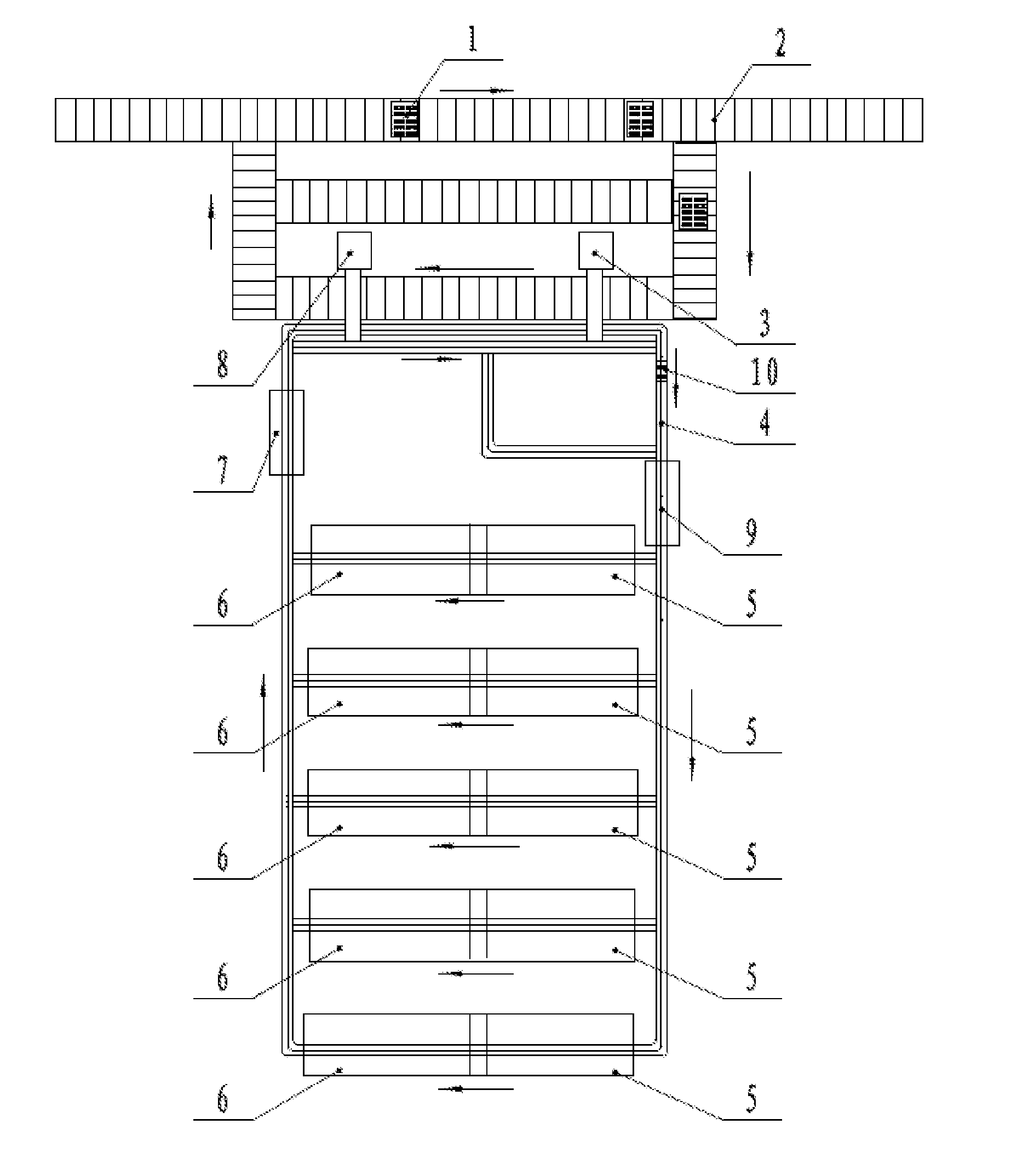
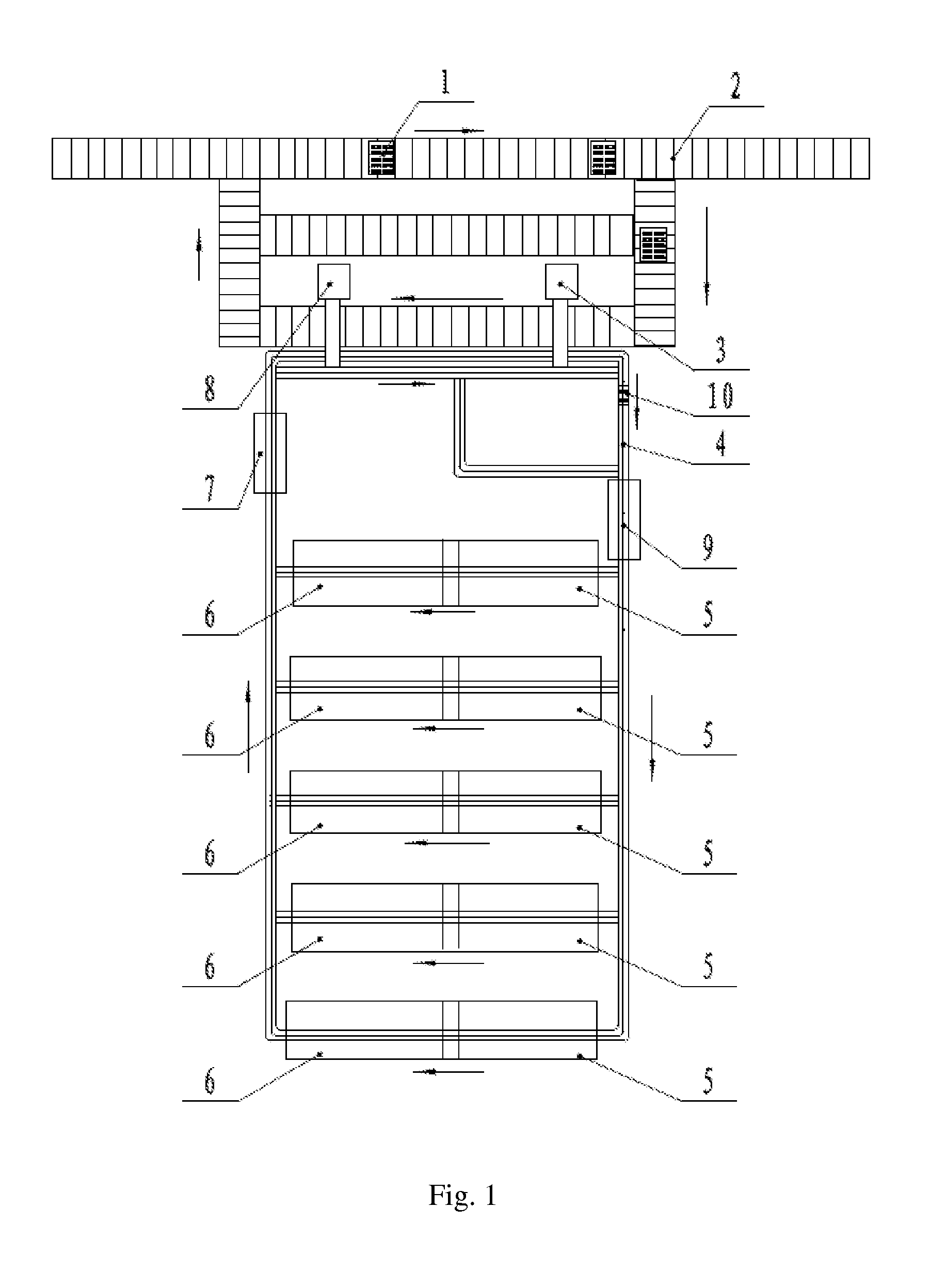
[0053]Referring to FIG. 1, which is a schematic structural view of the system for examining transformers full-automatically according to embodiments of the present application.

[0054]The system for examining transformers full-automatically according to embodiments of the present application includes: a material conveying line 2, a material charging device 3, an examination conveying line 4, an appearance inspection device 9, insulation test devices 5, error examining devices 6, a laser marking device 7, a material discharging device 8, and an examination management system.

[0055]The material conveying line 2, for conveying turnover boxes 1, delivers turnover boxes 1 charged with transformers to be examined from a storage system to a material charging station and delivers the turnover boxes 1 charged with transformers having been ...


PUM


Abstract

A full-automatic detecting system and method for a transformer. The system comprises a material delivery line; a feed device; a detection delivery line; insulating test devices; error detecting devices; a laser marking device; a discharge device; and a detection management system. The insulating test devices, the error detecting devices, and the laser marking device are sequentially arranged beside the detection delivery line. The material delivery line, the detection delivery line, and the devices work in coordination, to realize full-automatic detection of the transformer, avoid manual detection errors and improve the sorting accuracy.

Description

[0001]The present application claims the benefit of priority to Chinese Patent Application No. 201110198519.1, entitled “TRANSFORMER AUTOMATION EXAMINING SYSTEM”, filed with the Chinese State Intellectual Property Office on Jul. 14, 2011, the entire disclosure of which is incorporated herein by reference.[0002]The present application claims the benefit of priority to Chinese Patent Application No. 201110197022.8, entitled “BUSBAR TYPE CURRENT TRANSFORMER PRIMARY CORE-PENETRATING METHOD”, filed with the Chinese State Intellectual Property Office on Jul. 14, 2011, the entire disclosure of which is incorporated herein by reference.[0003]The present application claims the benefit of priority to Chinese Patent Application No. 201110208086.3, entitled “AUTOMATIC WIRE CONNECTING DEVICE FOR PRIMARY END OF MULTI-TURN TYPE TRANSFORMER”, filed with the Chinese State Intellectual Property Office on Jul. 22, 2011, the entire disclosure of which is incorporated herein by reference.[0004]The prese...

Claims


Application Information

Patent Timeline
IPC IPC(8): G01N35/00G01R31/01
CPCG01N35/00584G01R31/01H01F41/00G01R31/62
Inventor WANG, WEIZHU, JIONGZHANG, YANHUANG, JINJUANWU, JIANLI, XIONGZHOU, YONGJIAYAN, HUAJIANG
Owner STATE GRID ZHEJIANG ELECTRIC POWER
Learn More