Steam power plant with heat reservoir and method for operating a steam power plant

a technology of steam power plant and heat reservoir, which is applied in the direction of steam engine plants, steam accumulators, lighting and heating apparatus, etc., can solve the problems of complex known arrangement, reduce electric output, and easy control

Active Publication Date: 2013-11-14
GENERAL ELECTRIC TECH GMBH
View PDF17 Cites 4 Cited by
  • Summary
  • Abstract
  • Description
  • Claims
  • Application Information

AI Technical Summary

Benefits of technology

[0011]The design of the claimed invention is rather simple and easy to control. It is also suitable as a retrofit solution for existing power plants.
[0012]A further advantage of the claimed invention is that the electric output can be reduced to a rather great extent.
[0013]As with the steam power plant according to the invention the sensitive heat remains in the condensate and the condensate is temporarily stored in the heat reservoir, the apparative effort is low and the heat losses caused by the temporary storage of the condensate are also very low.
[0014]A further advantage of the steam power plant according to the invention is to be seen in that it is also possible to provide control energy by means of the heat reservoir, i.e. by either storing heat in the heat reservoir at short notice corresponding to the present demand or taking it from the heat reservoir.
[0015]A further advantage is to be seen in that the steam generator can be operated on a higher partial load level in weak load times and thus with an improved degree of efficiency.
[0016]A further very important advantage is to be seen in that even already existing steam power plants can generally be strengthened into a steam power plant according to the invention by integrating a heat reservoir, so that the advantages according to the invention can also be realized in already existing installations.

Problems solved by technology

This known arrangement is very complex and requires a multitude of heat exchangers as well as two heat reservoirs that are operated at different temperatures, i.e. approximately 190° C. and 520° C.

Method used


Image

  • Steam power plant with heat reservoir and method for operating a steam power plant
  • Steam power plant with heat reservoir and method for operating a steam power plant
  • Steam power plant with heat reservoir and method for operating a steam power plant

Examples


Embodiment Construction

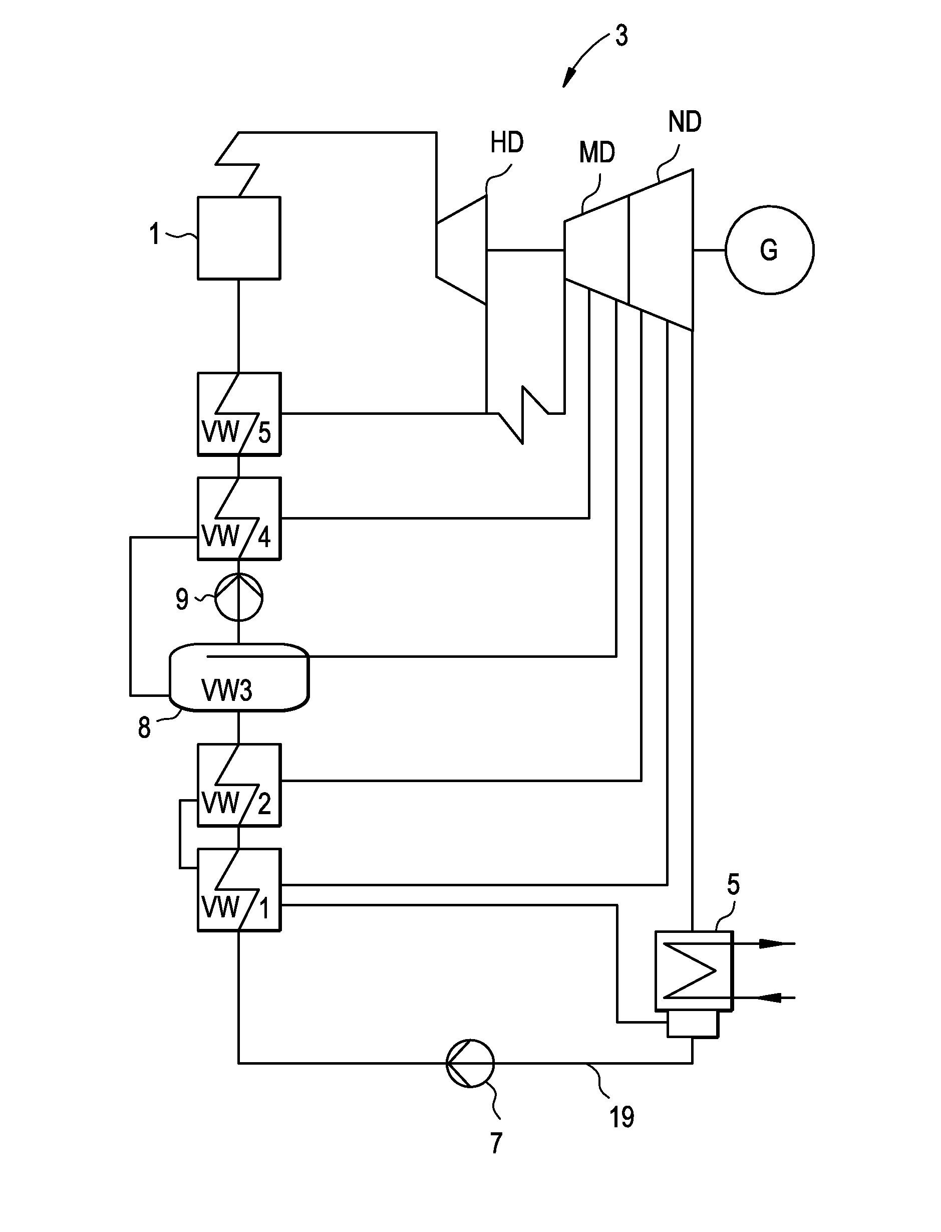
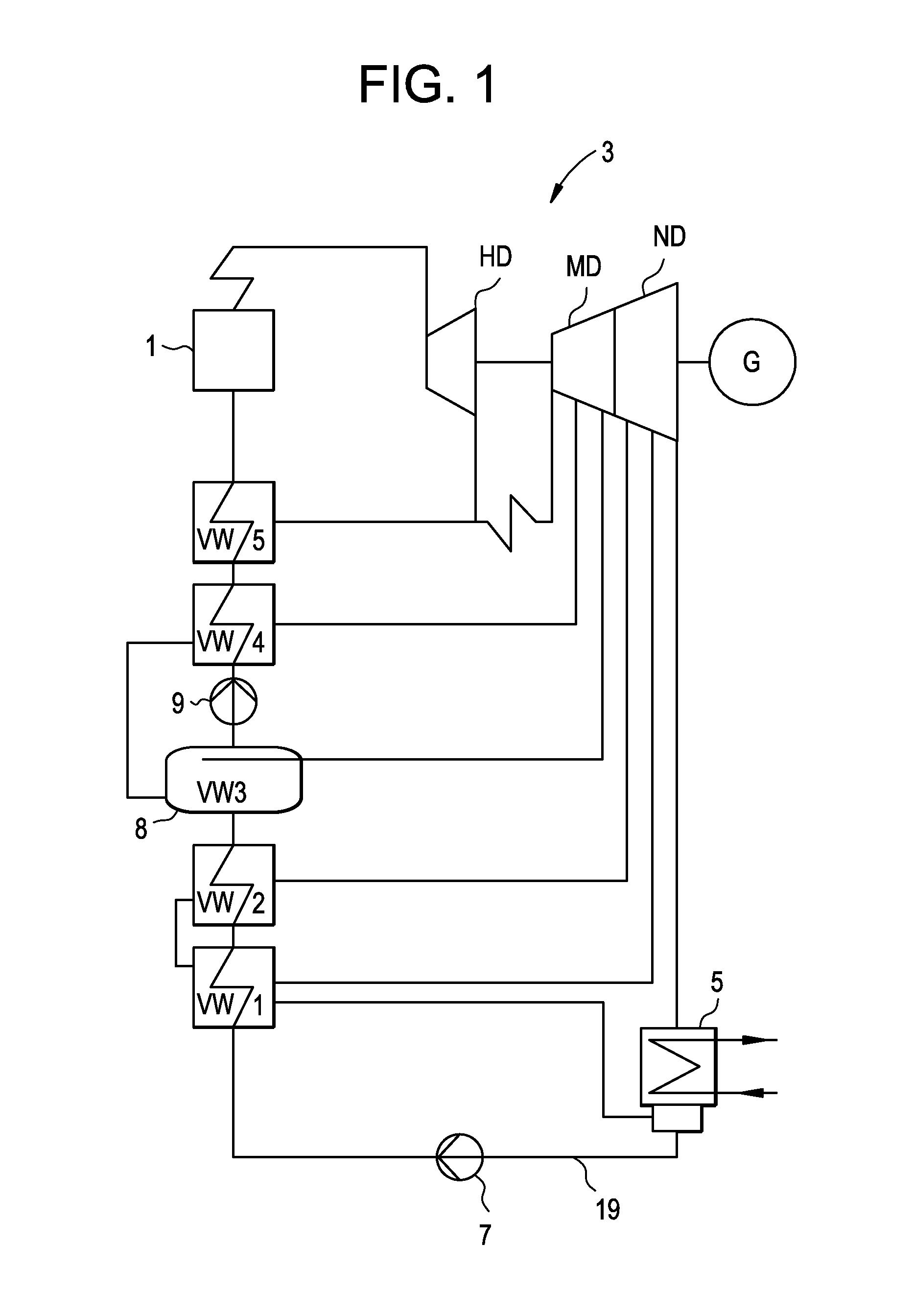
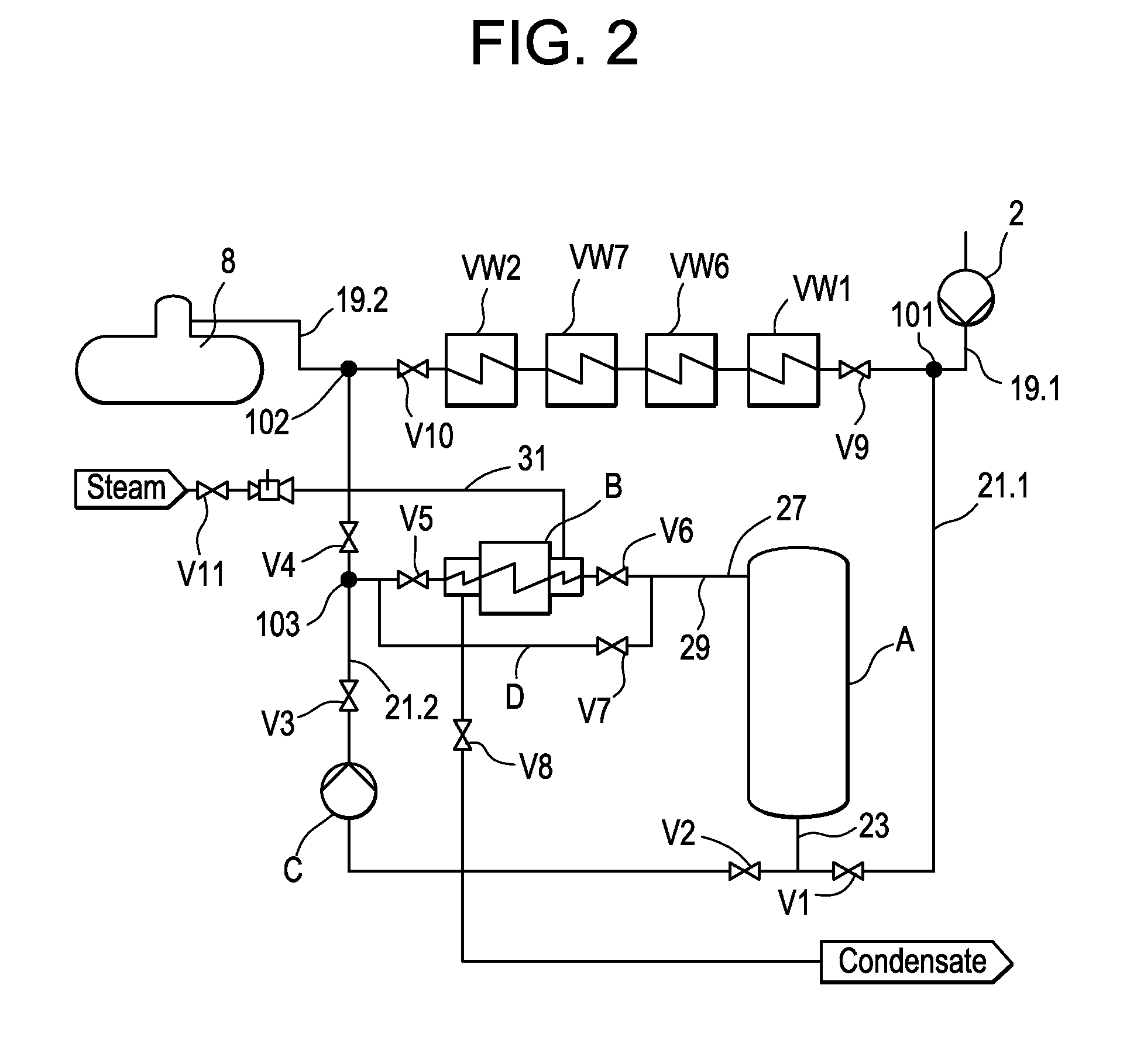
[0032]In FIG. 1 a steam power plant fuelled with fossils or biomass is represented as block diagram. FIG. 1 essentially has the purpose of designating the single components of the power plant and to represent the water-steam-cycle in its entirety. For reasons of clarity in the following figures only those parts of the water-steam-cycle are represented which are essential to the invention.

[0033]In a steam generator 1 under utilization of fossil fuels or by means of biomass out of the feed water live steam is generated, which is expanded in a steam turbine 3 and thus drives a generator G. Turbine 3 can be separated into a high-pressure part HD, a medium-pressure part MD and a low-pressure part ND.

[0034]After expanding the steam in turbine 3, it streams into a condenser 5 and is liquefied there. For this purpose a generally liquid cooling medium, as e.g. cooling water, is supplied to condenser 5. This cooling water is then cooled in a cooling tower (not shown) or by a river in the vici...


PUM


Abstract

A steam power plant is suggested having, parallel to the low-pressure passage (VW1 to VW2), a heat reservoir (A) which is loaded with preheated condensate in weak-load times. This preheated condensate is taken from the heat reservoir (A) for generating peak-load and inserted downstream of the low-pressure preheater passage (VW1 to VW2) into the condensate line (19.2) resp. the feed water container (8). Thus it is possible to quickly control the power generation of the power plant in a wide range without significantly having to change the heating output of the boiler of the steam generator (1). A steam power plant equipped according to the invention can thus be operated with bigger load modifications and also provide more control energy.

Description

CROSS REFERENCE TO RELATED APPLICATIONS[0001]This application claims the benefit of European Patent Application No.: 11187644.7, filed on Nov. 3, 2011, which is incorporated herein by reference in its entirety.SPECIFICATION[0002]Conventional steam power plant plants have a closed water-steam cycle. In the steam generator so much energy is added to the boiler feed water by combustion of a fossil fuel that it passes into the vaporous aggregate condition. This steam drives a generator via one or several steam turbines and afterwards is liquefied again in a condenser.[0003]As it is not possible to economically store electric energy in big scope, there were already considerations in the past aiming at storing thermal energy in a steam power plant in order to thereby increase the flexibility resp. adaption to grid requirements (peak load).[0004]It is known from U.S. Pat. No. 4,003,786 to arrange a chain of heat exchangers parallel to the preheater passage of the steam power plant. Via the...

Claims


Application Information

Patent Timeline
Patent Type & Authority Applications(United States)
IPC IPC(8): F01K3/00
CPCF01K3/004F01K3/265F01K7/22F01K7/40F01K13/02F22D3/00Y02E60/14
Inventor KITZMANN, EWALDSCHULE, VOLKERHEINTZ, JULIABOND, BENJAMIN
Owner GENERAL ELECTRIC TECH GMBH
Why Eureka
Try Eureka