Solar module and fabricating method thereof

a solar module and solar cell technology, applied in the field of solar modules, can solve the problems of reducing the light utilization of solar modules, reducing the and 70% of light irradiating outside the solar cell unit still cannot be used effectively, so as to improve the light utilization and generating efficiency of solar cell units.

Inactive Publication Date: 2013-11-14
AU OPTRONICS CORP
View PDF1 Cites 59 Cited by
  • Summary
  • Abstract
  • Description
  • Claims
  • Application Information

AI Technical Summary

Benefits of technology

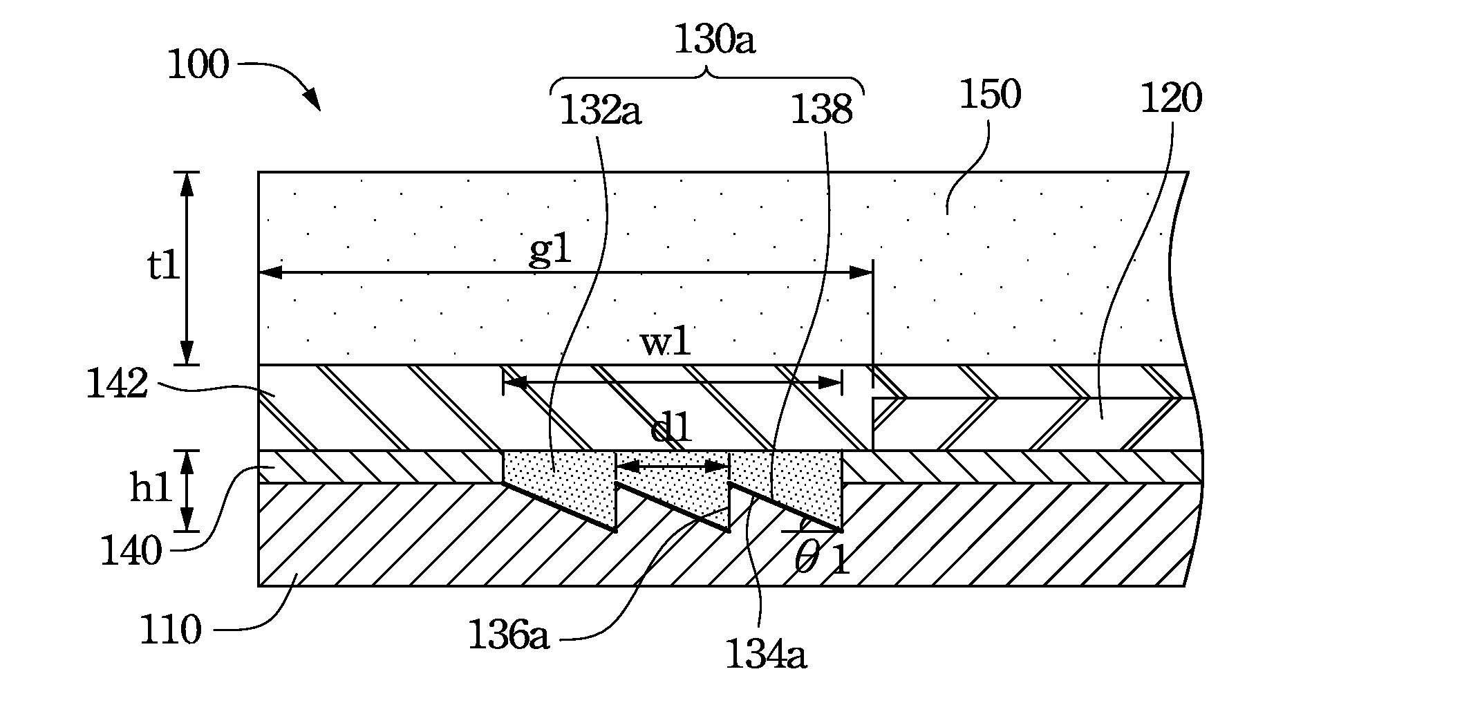
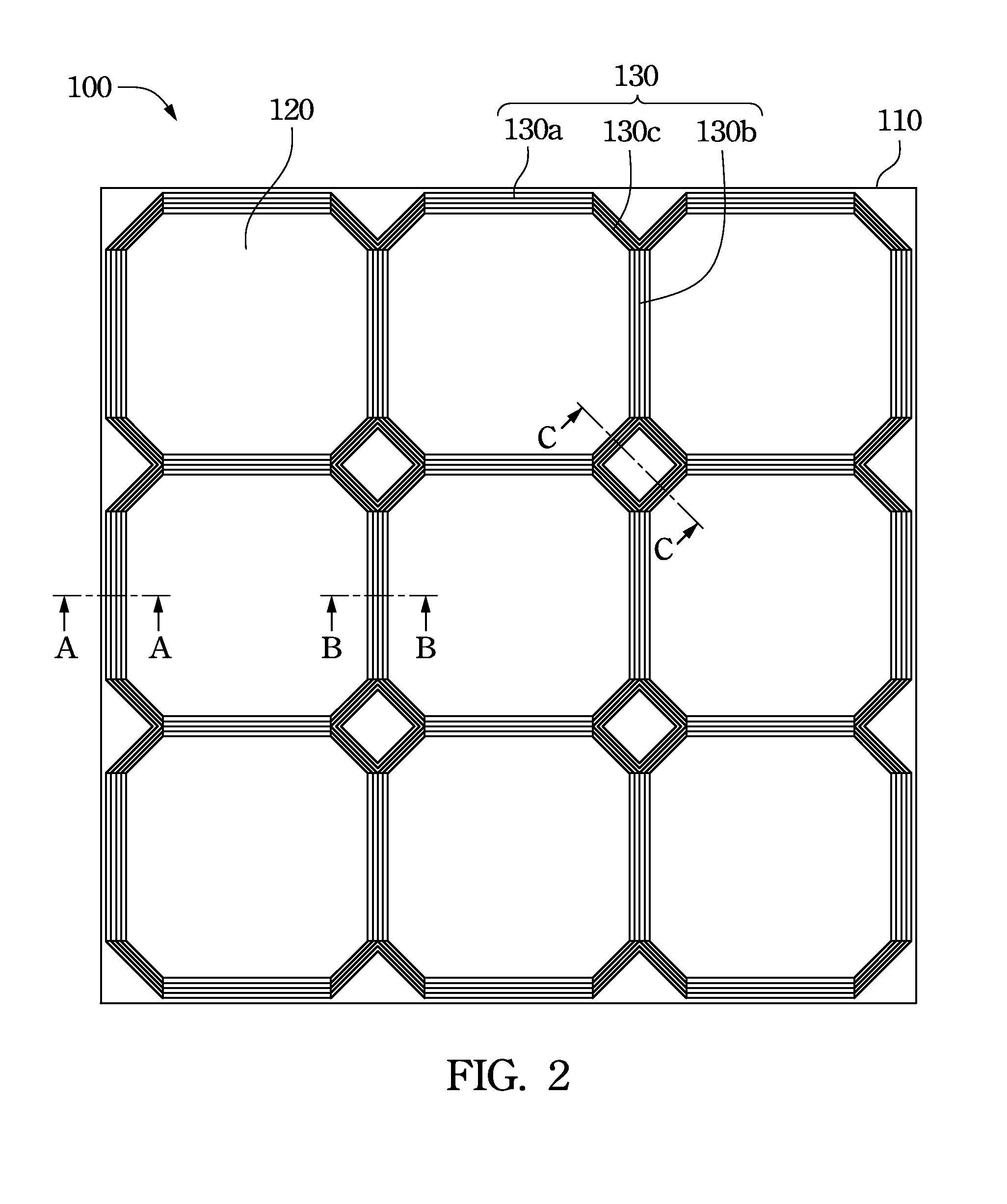
[0012]By using the reflecting structure disposed on one side of the solar cell units, light can be directed toward the solar cell units through reflection. According to the simulation results, about 65% of the light directly irradiating on the original gap can be reused. This improves the light utilization and the generating efficiency of the solar cell units.

Problems solved by technology

In recent years, since the crude oil stock all around the world is decreased year by year, the energy source problem has become the focus of global attention.
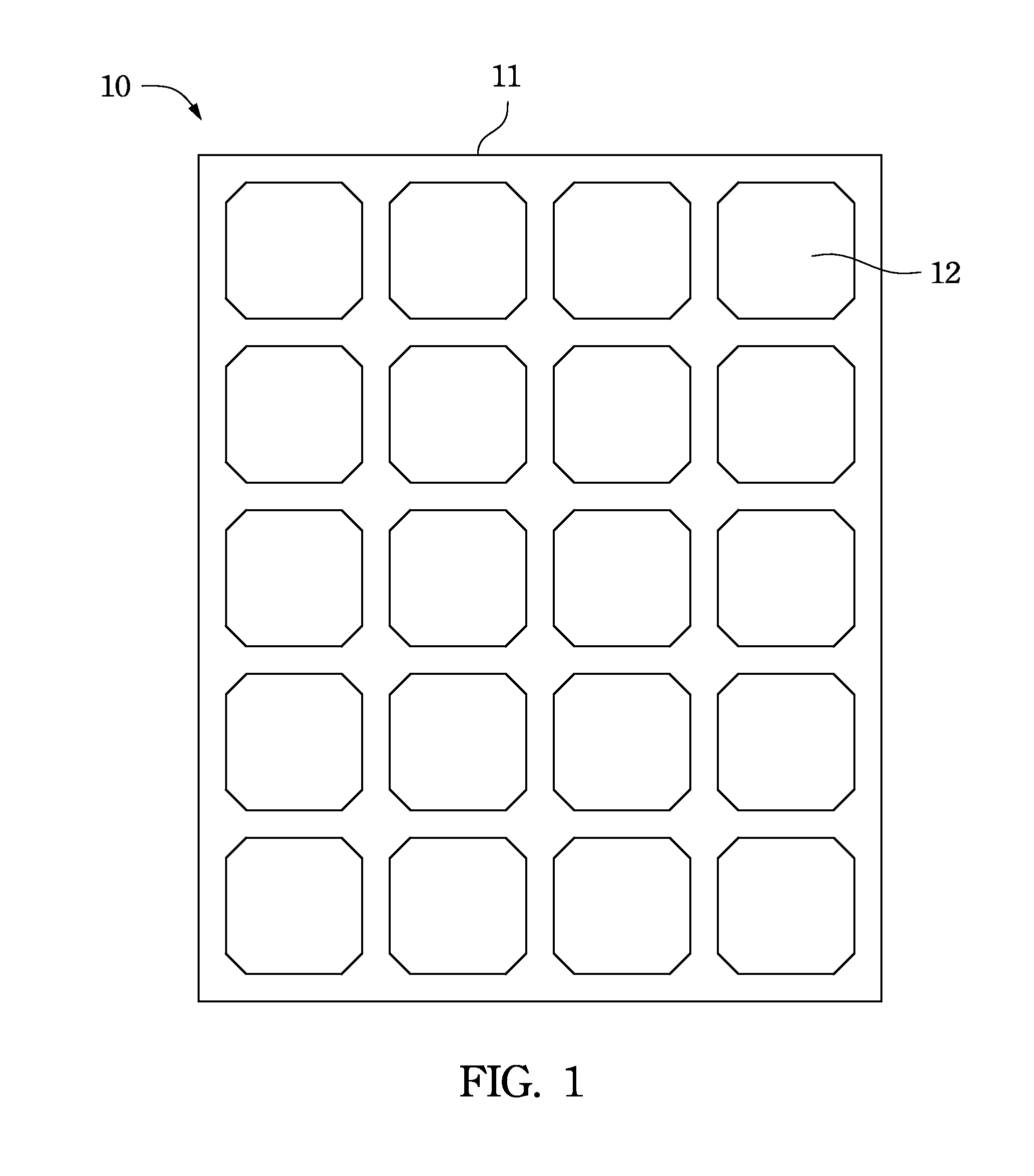
However, these preset gaps may reduce the light utilization of the solar module 10.
However even so, 70% of the light irradiating outside the solar cell unit still cannot be used effectively.
Therefore, the power generation efficiency of the solar module is affected.

Method used


Image

  • Solar module and fabricating method thereof
  • Solar module and fabricating method thereof
  • Solar module and fabricating method thereof

Examples


Embodiment Construction

[0029]The present invention is specifically described in the following examples. An example used at any position throughout the specification, including the usage of the examples using any terms discussed herein, is only used for illustration. Of cause, the example is not used for limiting the scope and meaning of the present invention or any terms in the examples. For those skilled in the art, various modification and variations can be made without departing from the spirit and scope of the present invention. Therefore, the scope of the present invention shall be defined by the appended claims. Additionally, the embodiments of the present invention may achieve plural technical effects, or the claims don't have to achieve all the aspects, advantages or features disclosed in the present invention. Those skilled in the art shall know that the embodiments and the elements thereof also include the inherent aspects, advantages or features that are not described expressly in the specifica...


PUM


Abstract

A solar module is disclosed, which includes a back plate, a reflecting structure, one or more solar cell units, a bottom sealant, a top sealant, and a transparent plate. The reflecting structure is disposed on the back plate. The reflecting structure has inclines and a reflector layer. The solar cell units are disposed on the back plate. The solar cell units are spatially separated from and adjacent to the reflecting structure. The inclines are tilted towards nearby solar cell units. The reflector layer is disposed on the incline for directing the light toward the solar cell unit through total internal reflection. The bottom sealant is disposed between the back plate and the solar cell units. The top sealant is disposed on the solar cell units, and the transparent plate is disposed on the top sealant. A method for fabricating the solar module is also disclosed.

Description

RELATED APPLICATIONS[0001]This application claims priority to China Application Serial Number 201210148958.6, filed May 14, 2012, which is herein incorporated by reference.BACKGROUND[0002]1. Technical Field[0003]The present invention relates to a solar module. More particularly, the present invention relates to a solar module with a reflecting structure.[0004]2. Description of Related Art[0005]In recent years, since the crude oil stock all around the world is decreased year by year, the energy source problem has become the focus of global attention. In order to solve the crisis of energy source depletion, the development and usage of various alternative energy sources become the urgent priority task. Since environmental awareness begins to prevail and the solar energy causes no pollution and is inexhaustible, the solar energy has become the biggest focus of attention in the relevant area. Therefore, in the position with sufficient sunshine, e.g., the buildings' roofs and squares, it...

Claims


Application Information

Patent Timeline
Patent Type & Authority Applications(United States)
IPC IPC(8): H01L31/052
CPCH01L31/0527Y02E10/52H01L31/0547H01L31/042
Inventor LIU, JOHNCHAN, I-MIN
Owner AU OPTRONICS CORP
Why Eureka
Try Eureka