Flexible stop for an acceleration sensor

Active Publication Date: 2013-11-14
ROBERT BOSCH GMBH
View PDF6 Cites 43 Cited by
  • Summary
  • Abstract
  • Description
  • Claims
  • Application Information

AI Technical Summary

Benefits of technology

[0007]Such a flexible stop in the Z-direction is already the subject matter of published European patent application document EP 2168809 A1 and published German patent application document DE 10 2008 043 753 A1. These designs have the disadvantage that the structures they propose have a relatively high space requirement, since the stop springs are realized in the thick functional layer of the micro-electro-mechanical system (MEMS) which has thicknesses greater than 10 μm, typically 15 μm to 20 μm. The great stiffness thereby caused must be offset by a correspondingly great length of the stop springs. This, in turn, is at the expense of precious space in the sensor core.
[0008]The present invention therefore has the objective of providing an improved acceleration sensor in which the flexible stops have a compact type of construction, so that the size of the sensor core is able to be kept small.
[0009]According to a first aspect of the present invention, the micromechanical acceleration sensor includes a seismic mass and a substrate which has a reference electrode, the seismic mass being deflectable in a direction perpendicular to the reference electrode, and the seismic mass having a flexible stop in the deflection direction, the flexible stop of the seismic mass including an elastic layer.
[0010]Producing the flexible stop by using an elastic layer is not limited by the stiffness of a thick MEMS functional layer, from which the seismic mass is constructed. This has the advantage that the flexible

Problems solved by technology

This could result in mechanical damage to the structure.
These designs have the disadvantage that the structures they propose have a relatively high space requirement, since the stop springs are realized in th

Method used


Image

  • Flexible stop for an acceleration sensor
  • Flexible stop for an acceleration sensor
  • Flexible stop for an acceleration sensor

Examples


Embodiment Construction

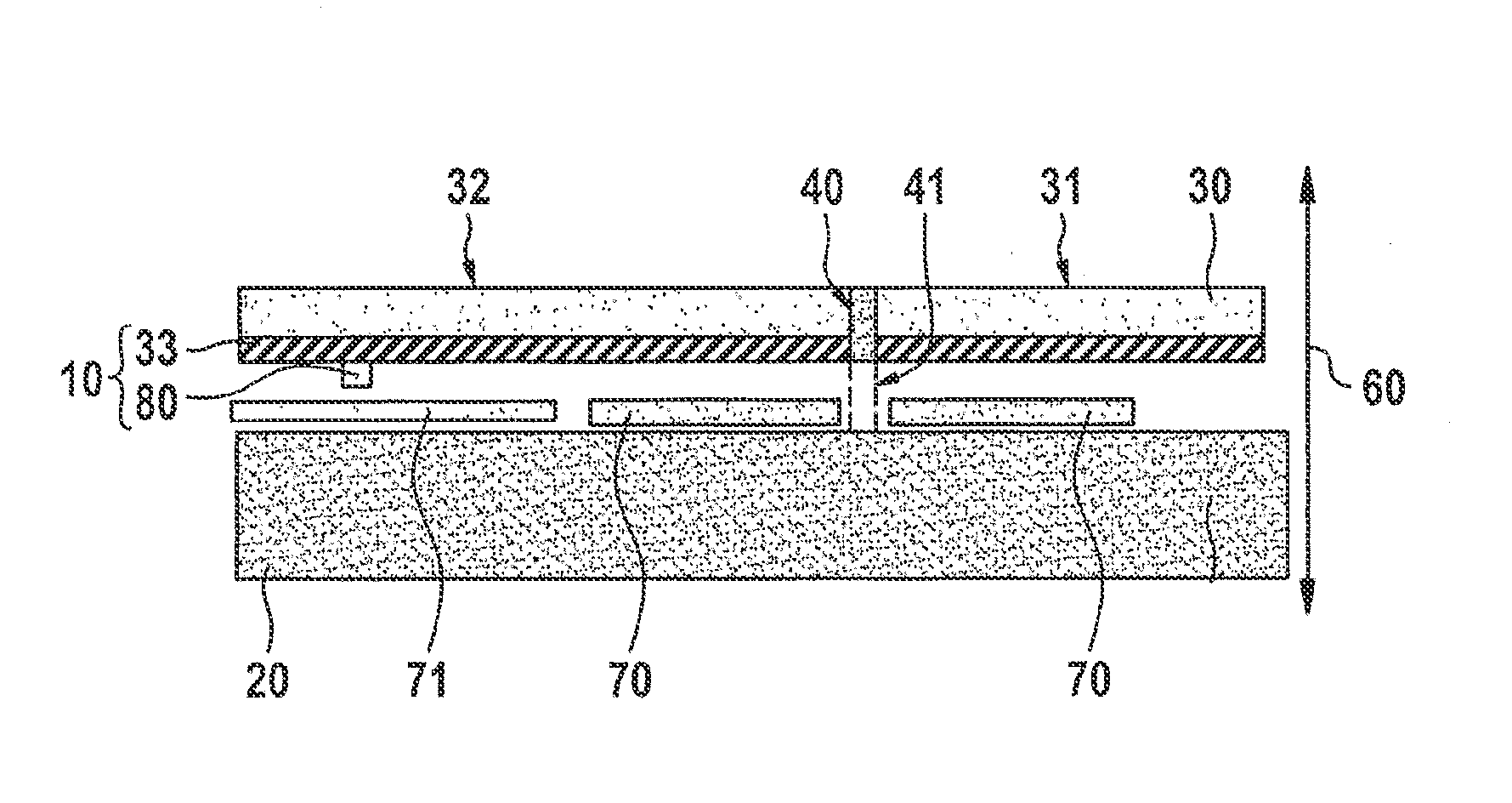
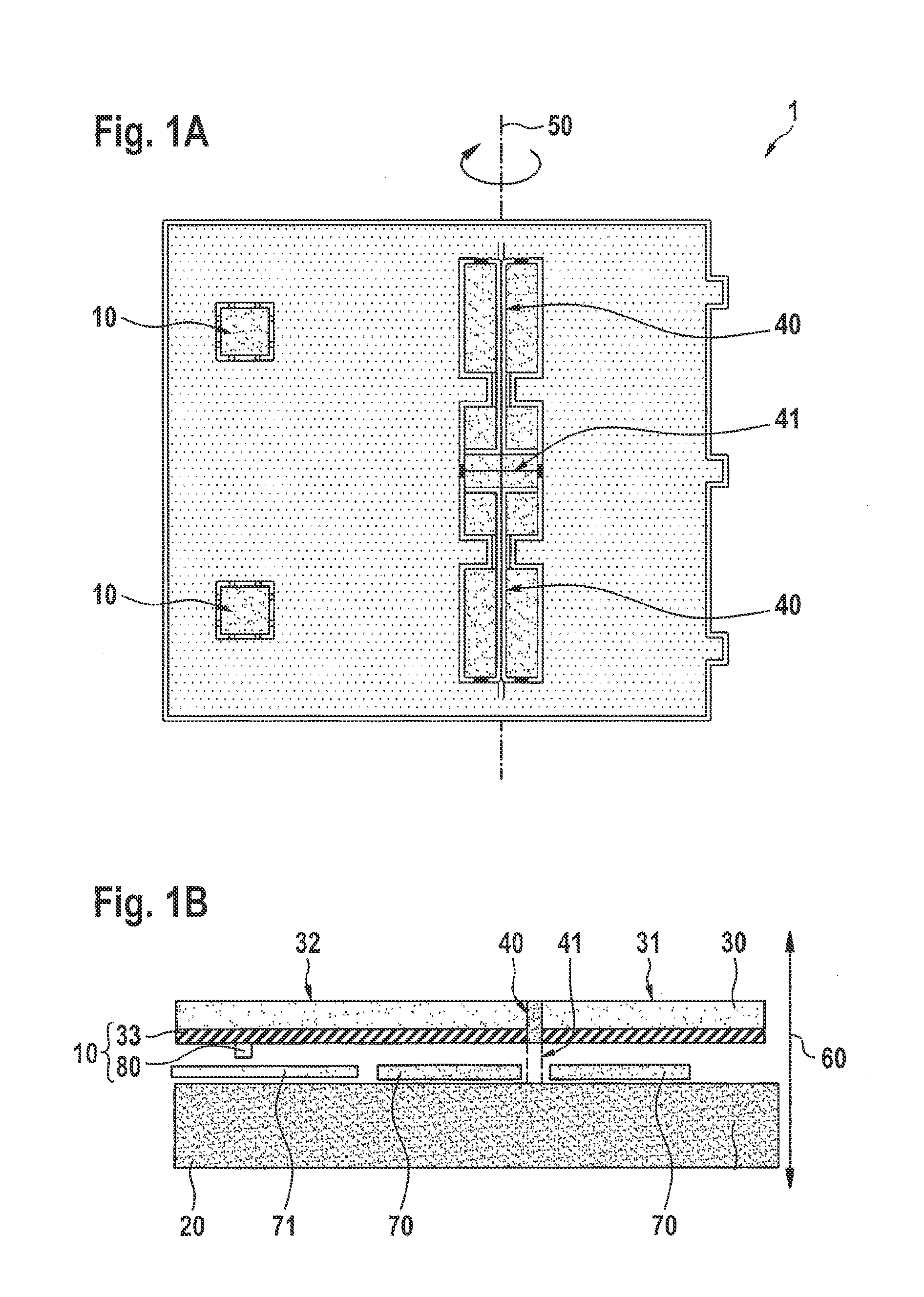
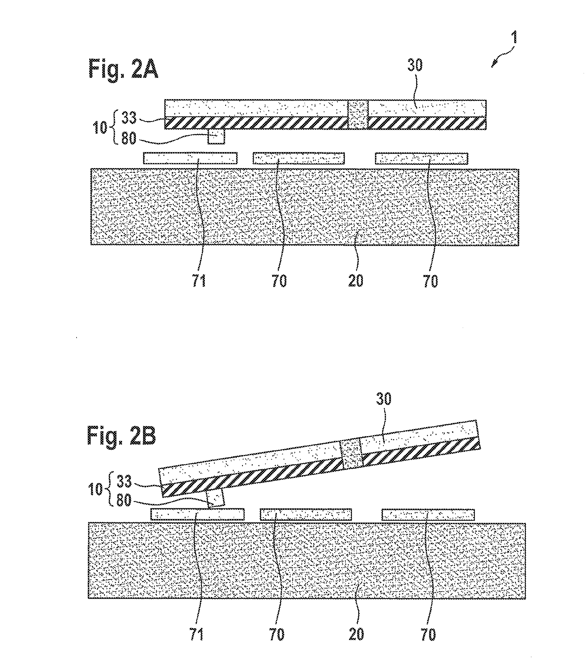
[0025]FIG. 1A and FIG. 1B show a first specific embodiment of a sensor system 1 in a schematic top view and a schematic lateral view. Sensor system 1 includes a substrate 20 and a seismic mass 30, seismic mass 30 taking the form of a rocker, that is, seismic mass 30 being joined elastically to substrate 20 via a formation 41 with the aid of a torsion-spring system 40 disposed centrally in terms of the seismic mass, and being deflectable relative to substrate 20 about a torsion axis 50. Seismic mass 30 has a first crossbar 31 and a second crossbar 32 specific to torsion axis 50, second crossbar 32 being longer than first crossbar 31, an uneven mass distribution thereby ensuing in the case of seismic mass 30 relative to torsion axis 50.

[0026]As a result of the uneven mass distribution, in response to an acceleration of sensor system 1 in a direction perpendicular to substrate 20, i.e., parallel to z-direction 60 indicated in FIG. 1B, seismic mass 30 undergoes a moment of rotation abou...


PUM


Abstract

A micromechanical acceleration sensor includes a seismic mass and a substrate that has a reference electrode. The seismic mass is deflectable in a direction perpendicular to the reference electrode, and the seismic mass has a flexible stop in the deflection direction. The flexible stop of the seismic mass includes an elastic layer.

Description

BACKGROUND OF THE INVENTION[0001]1. Field of the Invention[0002]The present invention relates to a micromechanical acceleration sensor having a substrate that has a reference electrode, and a seismic mass deflectable in a direction perpendicular to the substrate, a flexible stop being provided to limit the movement of the seismic mass.[0003]2. Description of the Related Art[0004]Modern sensors for measuring physical acceleration usually have a micromechanical structure made of silicon, also known as sensor core, and evaluation electronics. Sensor cores, which make it possible to measure an acceleration in a direction orthogonal to a main plane of the sensor core, are known as Z-sensors. Such sensors are used in the automotive sector, e.g., in ESP systems or perhaps in the field of wireless telephony. The sensor principle indicated is disclosed, inter alia, in published European patent document EP 0 244 581, which describes a micromechanical sensor for the automatic triggering of occ...

Claims


Application Information

Patent Timeline
IPC IPC(8): B81B3/00
CPCB81B3/0018B81B3/0051B81B2201/0235G01P2015/0871
Inventor CLASSEN, JOHANNESREINMUTH, JOCHENULLRICH, GUENTHER-NINO-CARLO
Owner ROBERT BOSCH GMBH
Why Eureka
Try Eureka