
Self-Calibrating Multi-Directional Security Luminaire and Associated Methods

a security luminaire and multi-directional technology, applied in the field of self-calibrating multi-directional security luminaires, can solve the problems of ineffective security cameras, inefficient security cameras, and inability to be deterred, and achieve the effect of increasing energy efficiency

Active Publication Date: 2013-11-14
LIGHTING SCI GROUP
View PDF7 Cites 21 Cited by
  • Summary
  • Abstract
  • Description
  • Claims
  • Application Information

AI Technical Summary

Benefits of technology

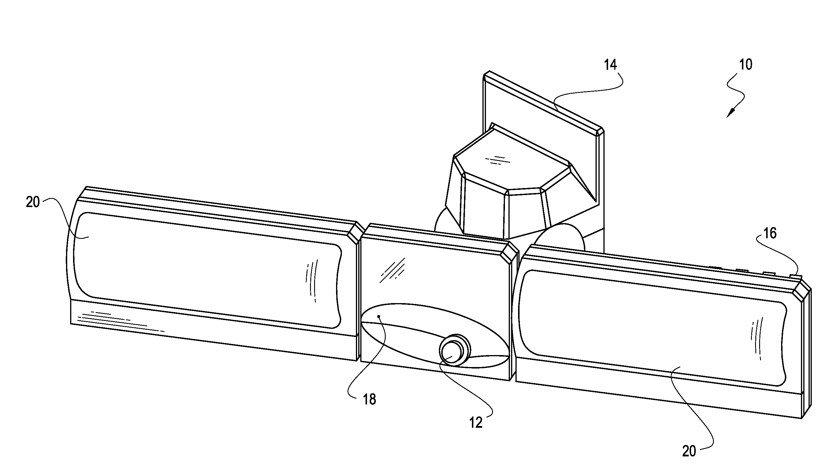
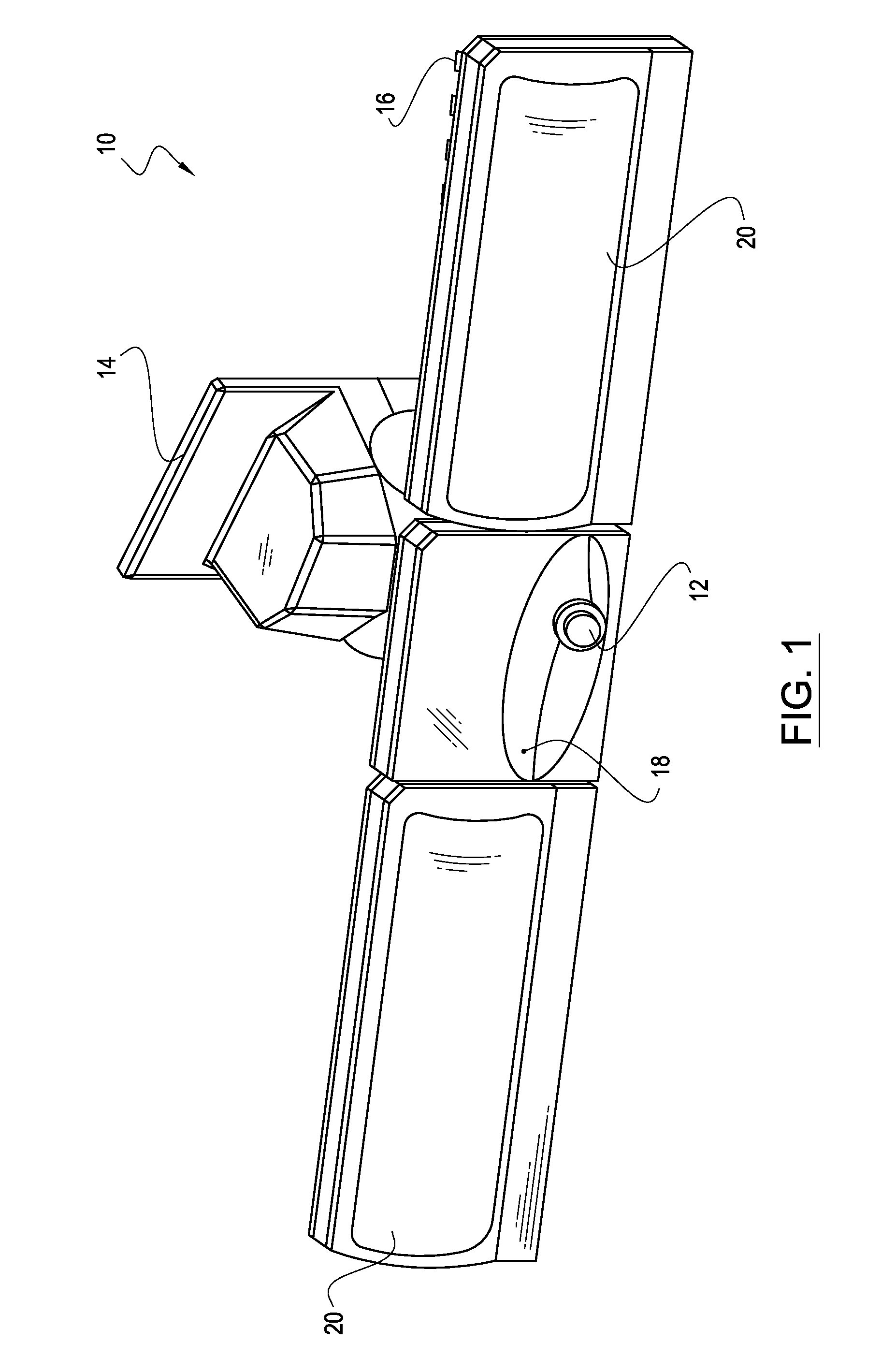
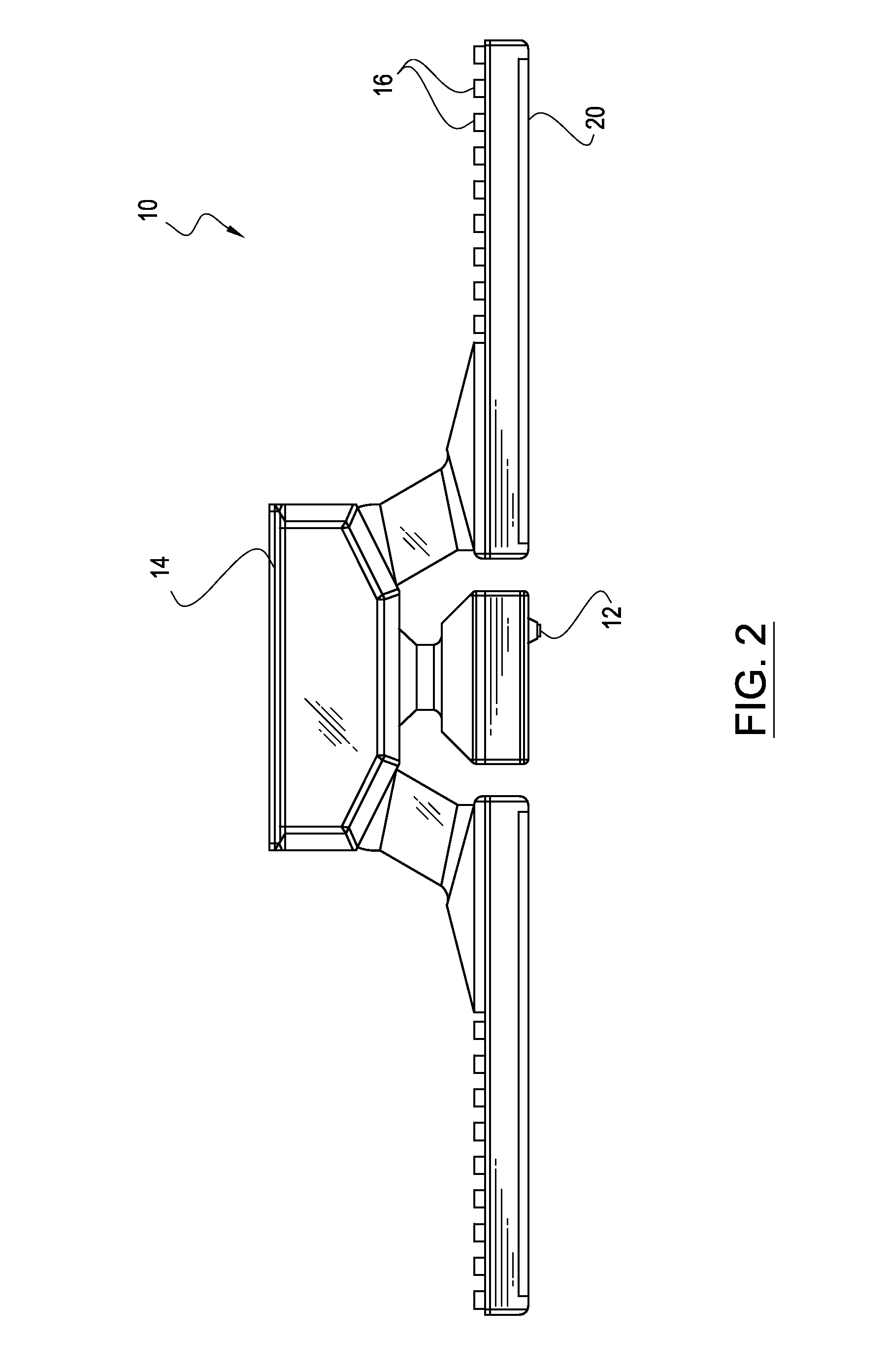
The present invention is for a luminaire that can adjust its light output to a minimum level, which reduces energy usage. It also directs its light without even needing to activate parts. The luminaire has two cameras and two sensors to detect objects in a target area. The light source arrays are positioned to minimize the overlap of the light emitted.

Problems solved by technology

Current security-based luminaires have several problems associated with them.
If they are activated too brightly all the time, they are inefficient.
If they are not bright enough, trespassers may not be deterred, and security cameras may be rendered useless.
However, environmental lighting changes, and luminaires may not adapt to the changing environment, rendering them even more inefficient.
Further, if security lights are activated by an intruder, floodlights may light areas that do not need to be lit as well as areas that need lighting to capture sight of the trespasser, thereby wasting energy.
If the lights are not properly positioned, the trespasser may still evade security measures.
Previous attempted solutions included actuating parts to move a security light, but these prove inefficient, as actuating parts require more power.

Method used


Image

  • Self-Calibrating Multi-Directional Security Luminaire and Associated Methods
  • Self-Calibrating Multi-Directional Security Luminaire and Associated Methods
  • Self-Calibrating Multi-Directional Security Luminaire and Associated Methods

Examples


Embodiment Construction

[0031]The present invention will now be described more fully hereinafter with reference to the accompanying drawings, in which preferred embodiments of the invention are shown. This invention may, however, be embodied in many different forms and should not be construed as limited to the embodiments set forth herein. Rather, these embodiments are provided so that this disclosure will be thorough and complete, and will fully convey the scope of the invention to those skilled in the art. Those of ordinary skill in the art realize that the following descriptions of the embodiments of the present invention are illustrative and are not intended to be limiting in any way. Other embodiments of the present invention will readily suggest themselves to such skilled persons having the benefit of this disclosure. Like numbers refer to like elements throughout.

[0032]In this detailed description of the present invention, a person skilled in the art should note that directional terms, such as “abov...


PUM


Abstract

A luminaire may include a wall mount and a driver circuit housing connected to the wall mount. The luminaire may also include a camera housing connected to the driver circuit housing, a light source housing connected to the camera housing, and a light source array that includes a plurality of light sources carried by the light source housing. The luminaire may include a prism, a heat sink in thermal communication with the light source array, and a camera carried by the camera housing. The luminaire may also include a sensor and a driver circuit carried by the driver circuit housing. The camera and / or the sensor may be configured to detect the presence and vicinity of an object in the target area. The light sources may be configured to emit light to illuminate the vicinity of the object sensed in the target area.

Description

RELATED APPLICATIONS[0001]This application claims the benefit of U.S. Provisional Patent Application Ser. No. 61 / 644,152 titled SELF-CALIBRATING MULTI-DIRECTIONAL SECURITY LUMINAIRE AND ASSOCIATED METHODS, filed on May 8, 2012, the entire contents of which are incorporated herein by reference. This application is also related to U.S. patent application Ser. No. 13 / 234,371 filed Sep. 16, 2011, titled COLOR CONVERSION OCCLUSION AND ASSOCIATED METHODS, U.S. patent application Ser. No. 13 / 107,928 filed May 15, 2011, titled HIGH EFFICACY LIGHTING SIGNAL CONVERTER AND ASSOCIATED METHODS, U.S. patent application Ser. No. 13 / 403,531 filed Feb. 23, 2012, titled CONFIGURABLE ENVIRONMENTAL CONDITION SENSING LUMINAIRE, SYSTEM AND ASSOCIATED METHODS, U.S. patent application Ser. No. 13 / 464,292 filed May 4, 2012, titled INTELLIGENT SECURITY LIGHT AND ASSOCIATED METHODS, and U.S. patent application Ser. No. 13 / 464,345 filed May 4, 2012, titled OCCUPANCY SENSOR AND ASSOCIATED METHODS, and U.S. Prov...

Claims


Application Information

Patent Timeline
IPC IPC(8): H05B37/02
CPCH05B37/0218F21S8/036F21V23/0478G08B13/19663Y02B20/40H05B47/11
Inventor HOLLAND, ERICIRVIN, JULIA SHARONTHOSTESON, ERICBURNS, BENJAMIN CHARLESBECK, JOHN
Owner LIGHTING SCI GROUP
Learn More