Coil structure and electromagnetic component using the same

a coil and coil technology, applied in the direction of transformer/inductance details, inductances, inductances with magnetic cores, etc., can solve the problem that the size of prior art electromagnetic components is difficult to shrink further, and achieve the effect of improving the coil structure of electromagnetic components, high yield and small siz

Inactive Publication Date: 2013-11-14
CYNTEC
View PDF7 Cites 64 Cited by
  • Summary
  • Abstract
  • Description
  • Claims
  • Application Information

AI Technical Summary

Benefits of technology

[0008]It is one object of the invention to provide an improved coil structure for

Problems solved by technology

However, the size of the prior art electromagn

Method used


Image

  • Coil structure and electromagnetic component using the same
  • Coil structure and electromagnetic component using the same
  • Coil structure and electromagnetic component using the same

Examples


Embodiment Construction

[0021]In the following description, numerous specific details are given to provide a thorough understanding of the invention. It will, however, be apparent to one skilled in the art that the invention may be practiced without these specific details. Furthermore, some well-known system configurations and process steps are not disclosed in detail, as these should be well-known to those skilled in the art. Therefore, the scope of the invention is not limited by the flowing embodiments and examples.

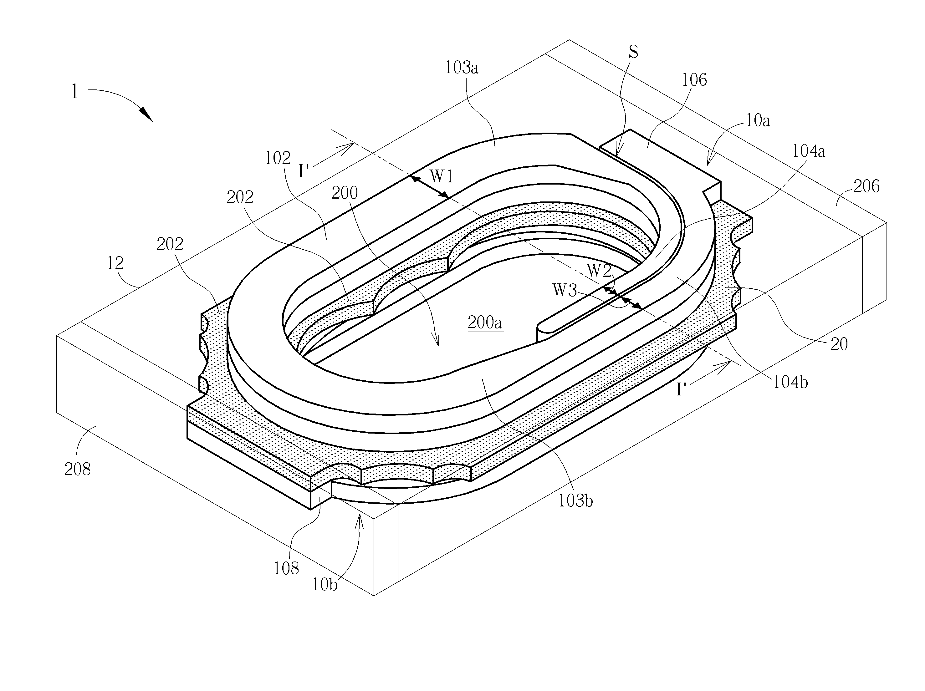
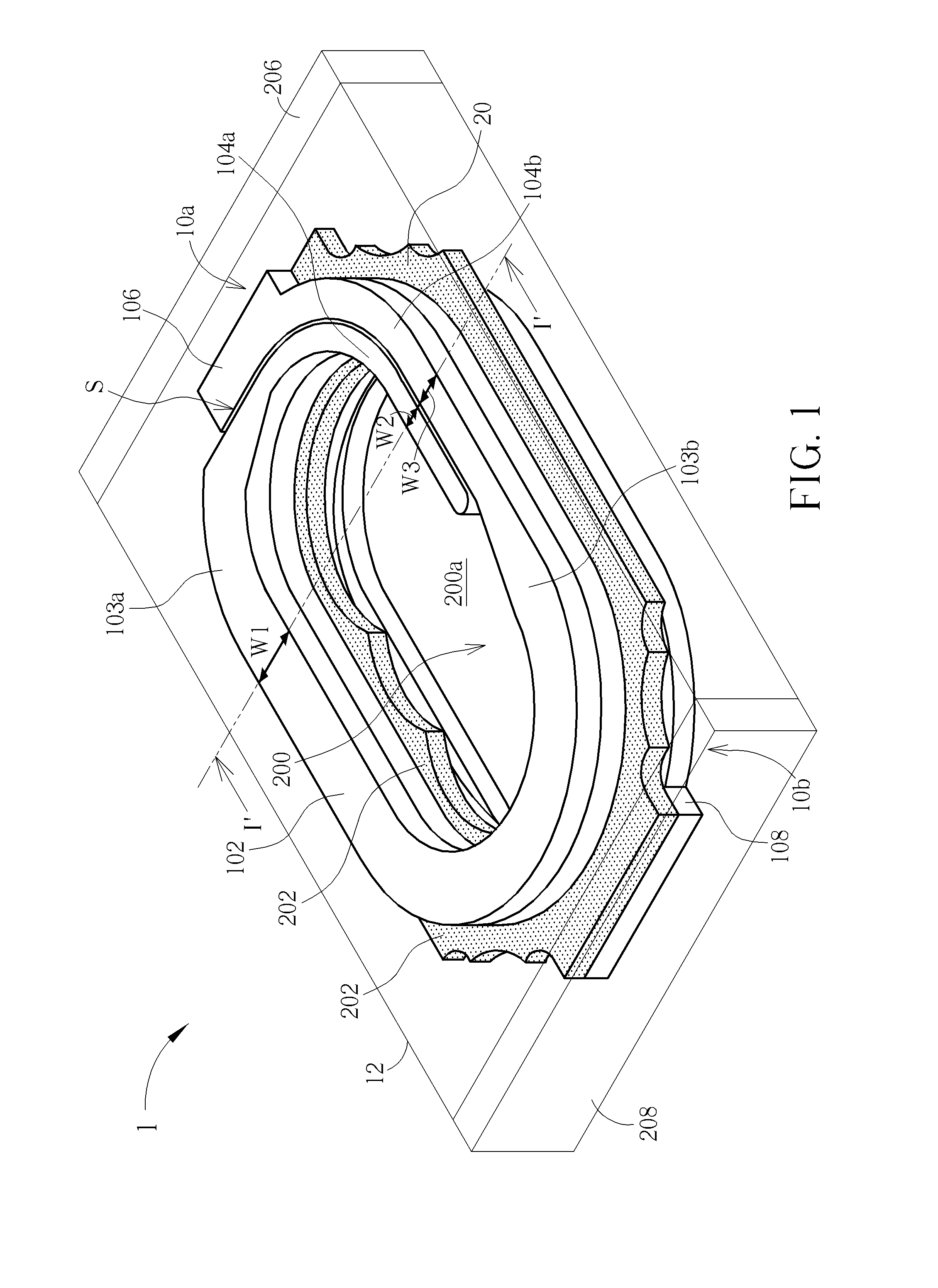
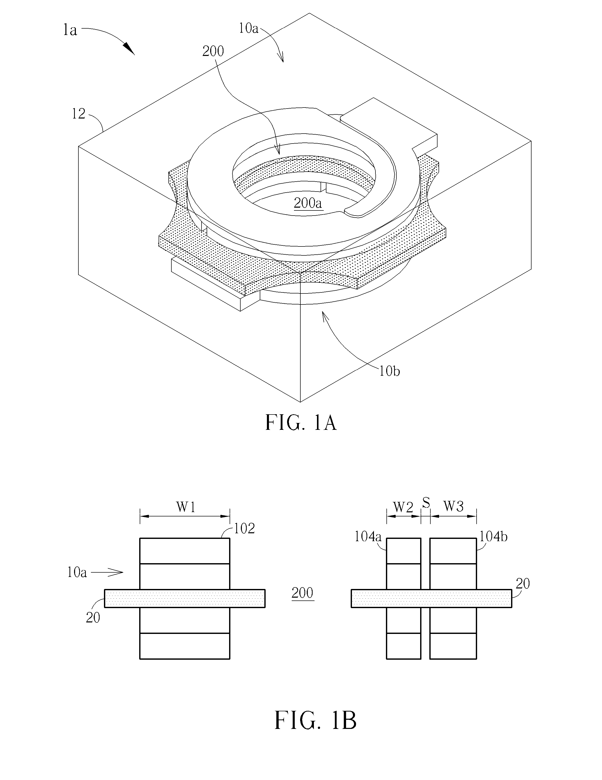
[0022]FIG. 1 is a schematic, perspective view showing an exemplary coil structure of an electromagnetic component in accordance with one embodiment of this invention. As shown in FIG. 1, the electromagnetic component 1, such as an inductor or choke coil, comprises a coil structure 10a situated on one side of a substrate 20. The substrate 20 may be an insulating substrate, but not limited thereto. The coil structure 10a may have a single-layered or multi-layered conductor film stack structure ...


PUM

PropertyMeasurementUnit
Lengthaaaaaaaaaa
Lengthaaaaaaaaaa
Widthaaaaaaaaaa

Abstract

An electromagnetic component including a multi-layer, spiral coil structure embedded in a molded body is disclosed. Each layer of the coil structure makes approximately one and a quarter turns of a winding. Each layer of the coil structure has a loose middle segment, two slim end segments overlapping each other with a spacing therebetween, and tapered neck segments respectively connecting the loose middle segment with the two slim end segments.

Description

CROSS REFERENCE TO RELATED APPLICATIONS[0001]This application claims priority from U.S. provisional application No. 61 / 637,277, filed Apr. 24, 2012.BACKGROUND OF THE INVENTION[0002]1. Field of the Invention[0003]The present invention relates to a coil structure for electromagnetic components and, more particularly, to a coil structure constructed.[0004]2. Description of the Prior Art[0005]As known in the art, electromagnetic components such as inductors or choke coils have typically been constructed by winding conductor wires about a cylindrical core. For example, insulated copper wires may be wrapped around the core. Structures of such electromagnetic components are usually designed to meet the surface mounting technology (SMT) or surface mounting device (SMD).[0006]The rapid advance toward electronic components having smaller size and higher performance in recent years is accompanied by strong demand for coil elements having smaller size and higher performance in terms of saturati...

Claims


Application Information

Patent Timeline
IPC IPC(8): H01F5/02
CPCH01F5/02H01F17/043H01F27/2804H01F27/292H01F17/04H01F27/2852H01F2027/2809H01F2017/048Y10T29/4902Y10T29/49002Y10T29/49071Y10T29/49073Y10T29/49075H01F5/003H01F41/04
Inventor CHANG, WEI-CHIENWU, CHIA-CHICHIANG, LANG-YIWU, TSUNG-CHANYEH, JIH-HSU
Owner CYNTEC
Why Eureka
Try Eureka