Temperature calibration methods and apparatus for optical absorption gas sensors, and optical absorption gas sensors thereby calibrated

a technology of temperature calibration and gas sensor, which is applied in the direction of measurement devices, material analysis through optical means, instruments, etc., can solve the problems of inability to determine, difficult to independently measure the change in optical properties of led and photodiodes with temperature, and design constraints of optical gas sensors

Active Publication Date: 2013-11-14
GAS SENSING SOLUTIONS
View PDF4 Cites 17 Cited by
  • Summary
  • Abstract
  • Description
  • Claims
  • Application Information

AI Technical Summary

Benefits of technology

[0025]However, the photodiode calibration data may comprise one or more parameters (of an algorithm relating a property of the photodiode output signal to a parameter related to photodiode temperature). The LED calibration data may comprise one or more parameters (of an algorithm relating a property of the LED, or an effect of a property of the LED on the response of the photodiode output signal to analyte gas concentration, with a parameter related to temperature). The step of determining the compensated signal may comprise calculating at least one algorithm taking into account at least one said parameter, for example, at least one said parameter concerning photodiode calibration and/or...

Problems solved by technology

However, it provides constraints on the design of optical gas sensors, as the LED and photodiode must be mounted close to each other in order to be in thermal equilibrium.
Thus, in practice, it has been considered difficult to independently measure the change in optical properties of the LED and photodiode with temperature.
If it was found that the photodiode output current dropped 10% due to ...

Method used


Image

  • Temperature calibration methods and apparatus for optical absorption gas sensors, and optical absorption gas sensors thereby calibrated
  • Temperature calibration methods and apparatus for optical absorption gas sensors, and optical absorption gas sensors thereby calibrated
  • Temperature calibration methods and apparatus for optical absorption gas sensors, and optical absorption gas sensors thereby calibrated

Examples


Embodiment Construction

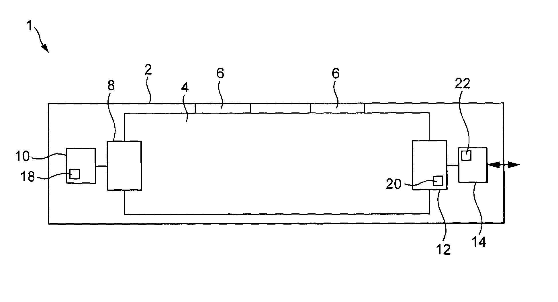
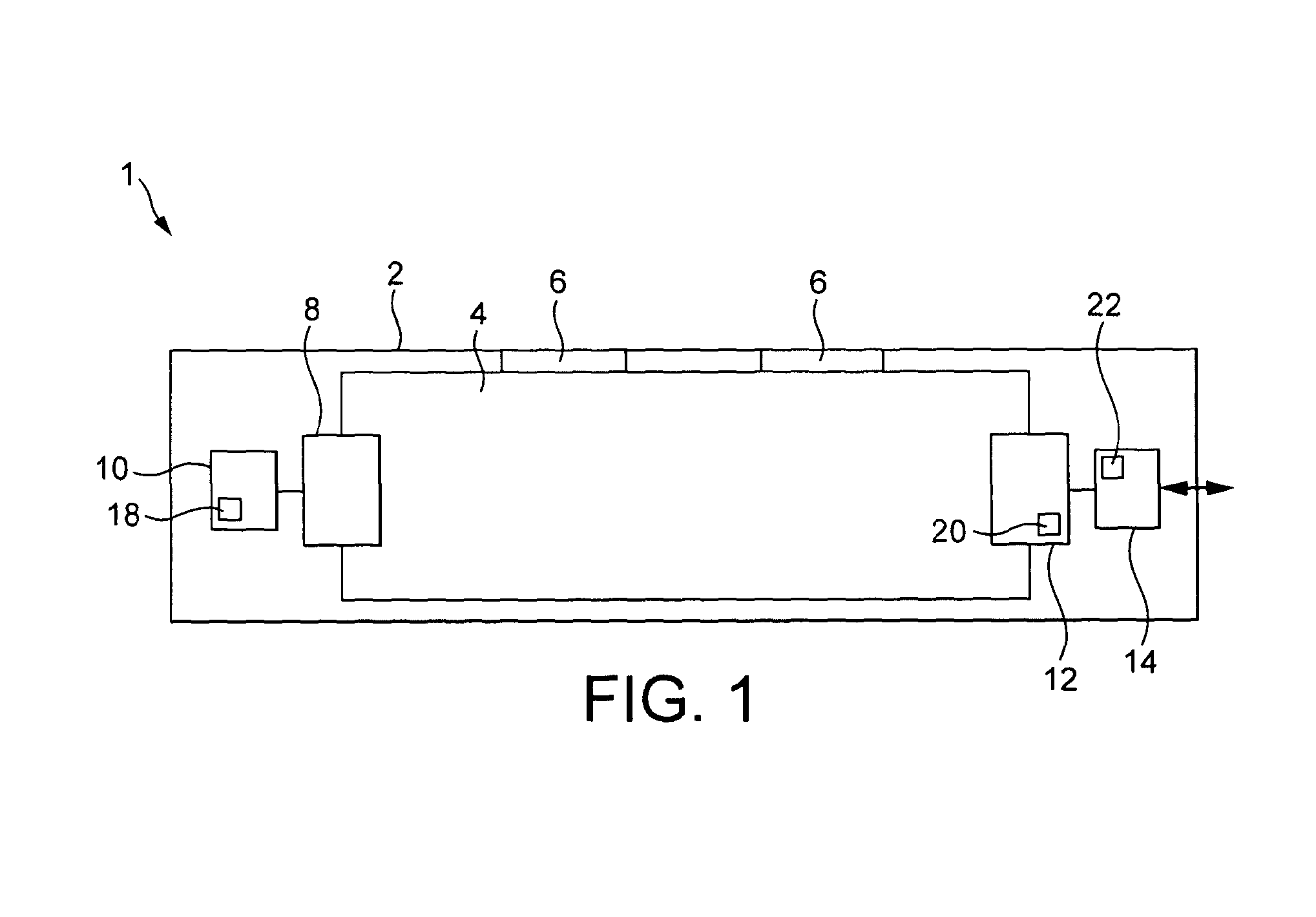
[0048]With reference to FIG. 1, an optical absorption gas sensor 1 has a body 2 defining a gas sample chamber 4, into which a gas sample can pass by diffusion through one or more apertures 6. A light emitting diode 8 functions as a light source, and is driven by an LED driving circuit 10. A photodiode 12 functions as a photosensor, and has an output current dependent on the light which falls on the photodiode junction. The current from the photodiode is amplified and processed by a control and compensation circuit 14 including a microcontroller, which provides a compensated signal through an output 16 which is related to the concentration of analyte gas in the gas sample chamber.

[0049]The gas sample chamber may have any of a large number of configurations known to those skilled in the art, and typically includes a reflective inner surface, so that light from the LED may be reflected one or more times between the LED and a photodiode. An example configuration is illustrated in FIG. 7...


PUM


Abstract

An optical absorption gas sensor has an LED light source and a photodiode light detector, a temperature measuring device for measuring the LED temperature and a temperature measuring device for measuring the photodiode temperature. The sensor is calibrated by measuring the response of photodiode current at zero analyte gas concentration and at a reference analyte gas concentration. From these measurement, calibration data taking into account the effect of photodiode temperature on the sensitivity of the photodiode and, independently, the effect of changes in the spectrum of light output by the LED on the light detected by the photodiode with LED temperature can be obtained. Calibration data is written to memory in the gas sensor and in operation of the gas sensor, the output is compensated for both LED and photodiode temperature. The LED and photodiode can therefore be relatively far apart and operate at significantly different temperatures allowing greater freedom of optical pathway design.

Description

FIELD OF THE INVENTIONBackground to the Invention[0001]The invention relates to the field of optical absorption gas sensors which employ an LED (for example, an infra-red LED) as a source of light and a photodiode as a detector of light.Background to the Invention[0002]Optical absorption gas sensors include both a source of light and a light detector. Light from the source is directed through a gas sample and detected by the light detector. The concentration of an analyte gas in the gas sample can be determined from the absorption of light by the analyte gas. Typically, either the source will emit light predominantly within a wavelength range corresponding to absorption lines of the intended analyte, or the detector will be sensitive to light predominantly within a wavelength range corresponding to absorption lines of the intended analyte, either due to the inherent properties of the light sensitive transducer which is employed or due to the presence of a wavelength filter which sel...

Claims


Application Information

Patent Timeline
IPC IPC(8): G01N21/27
CPCG01N21/27G01N21/274G01N21/3504G01N33/0006G01N2201/1211G01N2201/12723G01N2201/12753G01N2201/12792
Inventor MACGREGOR, CALUM JOHNGIBSON, DESMOND ROBERT
Owner GAS SENSING SOLUTIONS
Why Eureka
Try Eureka