Opt0-mechanical apparatus adapted for mounting optical elements with small cross sections

a technology of optical elements and mechanical equipment, applied in the field of optical mechanical equipment, can solve the problems of reducing the optical field of view of the new apparatus, reducing the efficiency of such new apparatus, and the method of retaining the optical device in the housing can fail during use, so as to achieve reliable mechanical connection, maximize the field of view, and ensure the effect of mechanical connection

Active Publication Date: 2013-11-14
INTUITIVE SURGICAL OPERATIONS INC
View PDF7 Cites 19 Cited by
  • Summary
  • Abstract
  • Description
  • Claims
  • Application Information

AI Technical Summary

Benefits of technology

[0013]Therefore it is an object of this invention to provide an opto-mechanical assembly that provides a reliable mechanical connection between an optical element and a housing for carrying that optical element.
[0015]Still another object of this invention is to provide an opto-mechanical assembly that provides a reliable mechanical connection for an optical supporting housing and that maximizes field of view.
[0016]Yet another object of this invention is to provide an opto-mechanical assembly that provides a reliable mechanical connection for an optical element in a supporting housing and that is commercially and technologically feasible.
[0017]In accordance with one aspect of this invention, an opto-mechanical assembly as at last one end and comprises an optical element, a mechanical housing, a cavity in at least one of said optical element and mechanical housing, and adhesive in each cavity. The optical element has first and second polished end surfaces and an intermediate body portion through which light passes and has a given outer periphery and a given cross section transverse to an optical axis for the opto-mechanical assembly. The mechanical housing positions the optical element along the optical axis at the one end so that the first polished end surface of the optical element is substantially flush with the one end of the mechanical housing. A cavity is formed in one of the optical element and mechanical housing. The mechanical properties of the adhesive in the cavity enable the adhesive to lock the optical element axially within the mechanical housing independently of any adhesive bond.

Problems solved by technology

As the demand for smaller and smaller diameter lenses continues to increase, new problems have emerged that can detract from the efficacy of such new apparatus.
First, the housing can overlie the imaging surface of an optical element and thereby reduce the optical field of view for that apparatus.
Second, the method by which the optical device is retained in the housing can fail during use.
Such opto-mechanical assemblies can be subjected to environmental conditions that create forces on the bonds produced by the adhesive material.
Also, if the lens 11 were to separate from the housing 12, negative consequences for the procedure being performed with the assembly could result.
Thus, as will be apparent to those skilled in the art, the specific opto-mechanical assembly in FIG. 1 provides a maximum field of view and smooth distal surface, but a less than optimal resistance to shock and other environmental factors.
Cleaning of the exterior surface, which is not smooth, is therefore more difficult due to the interior angles.
For an opto-mechanical assembly of a given size, the cost of adding in separate locking elements and fastening them in a secure manner increases the expense of manufacture.
Moreover, as the apparatus size decreases, manufacturing complexity and concomitant costs increase.
In fact for lens assemblies that are very small, for example less than 2 mm, the cost of adopting such a construction technique can become commercially and technically prohibitive.

Method used


Image

  • Opt0-mechanical apparatus adapted for mounting optical elements with small cross sections
  • Opt0-mechanical apparatus adapted for mounting optical elements with small cross sections
  • Opt0-mechanical apparatus adapted for mounting optical elements with small cross sections

Examples


Embodiment Construction

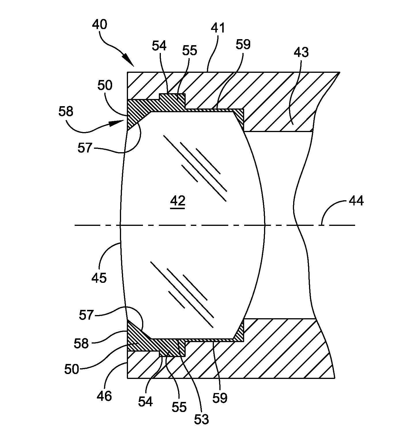
[0026]In FIG. 3 an opto-mechanical assembly 40 includes a mechanical housing 41 and an optical element in the form of a bi-convex lens 42. As known, such lenses have first and second end surfaces and an intermediate body portion through which light passes. A specific optical element may have a circular or polygonal cross section and other peripheral features. In FIG. 3 the bi-convex lens is cylindrical.

[0027]The mechanical housing 41 includes an integral positioning band 43 that forms an annular stop for blocking any proximal shift of the lens 42 (i.e., to the right in FIG. 3). The housing 41 also supports the lens 42 along an optical axis 44. The positioning band 43 locates the lens 42 so its distal surface 45 is flush with a distal end surface 46 of the housing 41.

[0028]In accordance with this invention, adhesive 50 is disposed about the periphery of the lens 42 and the corresponding surfaces of the housing 41. More specifically and referring to FIGS. 3 and 4, the housing 41 inclu...


PUM


Abstract

An opto-mechanical assembly including a housing and an internally supported optical element, such as a lens, mounted along an axis. At least one of the housing and optical element includes a radially extending chamber. Adhesive disposed in the chamber interacts with the housing and the optical element to prevent axial motion between the optical element and housing.

Description

CROSS REFERENCE TO RELATED APPLICATION[0001]This application claims priority from U.S. Provisional Patent Application No. 61 / 646,760 for Opto-Mechanical Apparatus Adapted for Mounting Optical Elements with Small Cross Sections filed May 14, 2012 and assigned to the application of this inventionBACKGROUND OF THE INVENTION[0002]1. Field of the Invention[0003]This invention generally relates to optical-mechanical apparatus and more specifically to opto-mechanical apparatus having a small cross section that includes a housing and an optical element.[0004]2. Description of Related Art[0005]A significant effort has been made and continues to be made toward the development of opto-mechanical apparatus with increasingly smaller transverse cross sections. This is particularly true in the medical field where diagnosis and related treatment regimens for endoscopic devices is expanding with the introduction of smaller, reliable and reasonably priced opto-mechanical apparatus. Presently there ar...

Claims


Application Information

Patent Timeline
Patent Type & Authority Applications(United States)
IPC IPC(8): G02B7/02
CPCG02B7/02G02B7/025G02B23/2476A61B1/00096A61B1/0011
Inventor BREIDENTHAL, ROBERT S.CYR, RICHARDCHAMBERS, DAVIDFORKEY, JOSEPH N.ROSS, ROBERT N.VOLK, BRIAN E.
Owner INTUITIVE SURGICAL OPERATIONS INC
Why Eureka
Try Eureka