Optical quality control system

a quality control system and optical quality technology, applied in the field of cooking devices, can solve the problems of complex systems disclosed in the above references, and are likely to be subject to frequent and expensive repairs and adjustments, and achieve the effect of simple and reliable system and method, simple and reliable device and method

Active Publication Date: 2013-11-14
WELBILT DEUT GMBH
View PDF102 Cites 103 Cited by
  • Summary
  • Abstract
  • Description
  • Claims
  • Application Information

AI Technical Summary

Benefits of technology

[0015]The systems disclosed in the above references are quite complex and likely subject to frequent and expensive repairs and adjustments. Also, the above references do not reflect systems or methods that can serve to confirm that a cooking cycle / program has attained the quality of cooked product that is expected. Therefore, a simple and reliable device and method to ensure that food product is subject to the correct cooking cycle / program and that can monitor the quality of the cooked state of food product(s) is still needed. According to the present disclosure, such a simple and reliable system and method are provided.
[0016]It is an object of the present disclosure to provide inspection systems for a cooking device, in particular a commercial cooking device, as well as methods of operating the same that are technically simple, reliable and easy to handle for an operator.

Problems solved by technology

The systems disclosed in the above references are quite complex and likely subject to frequent and expensive repairs and adjustments.
Also, the above references do not reflect systems or methods that can serve to confirm that a cooking cycle / program has attained the quality of cooked product that is expected.
This is especially so if that cooking cycle / program for whatever reason was insufficient for or did not produce the quality of, e.g., the outer appearance of the cooked food product, or surface temperature of the cooked food product, that was desired.

Method used


Image

  • Optical quality control system
  • Optical quality control system
  • Optical quality control system

Examples


Embodiment Construction

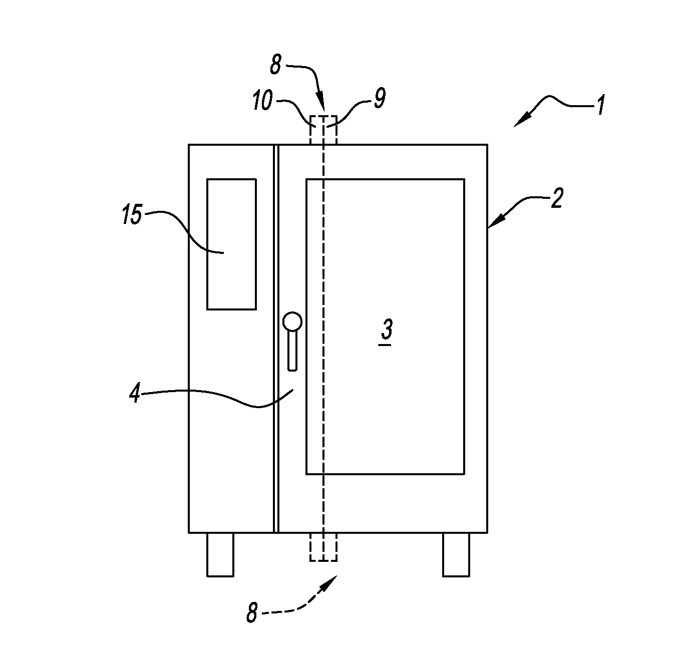
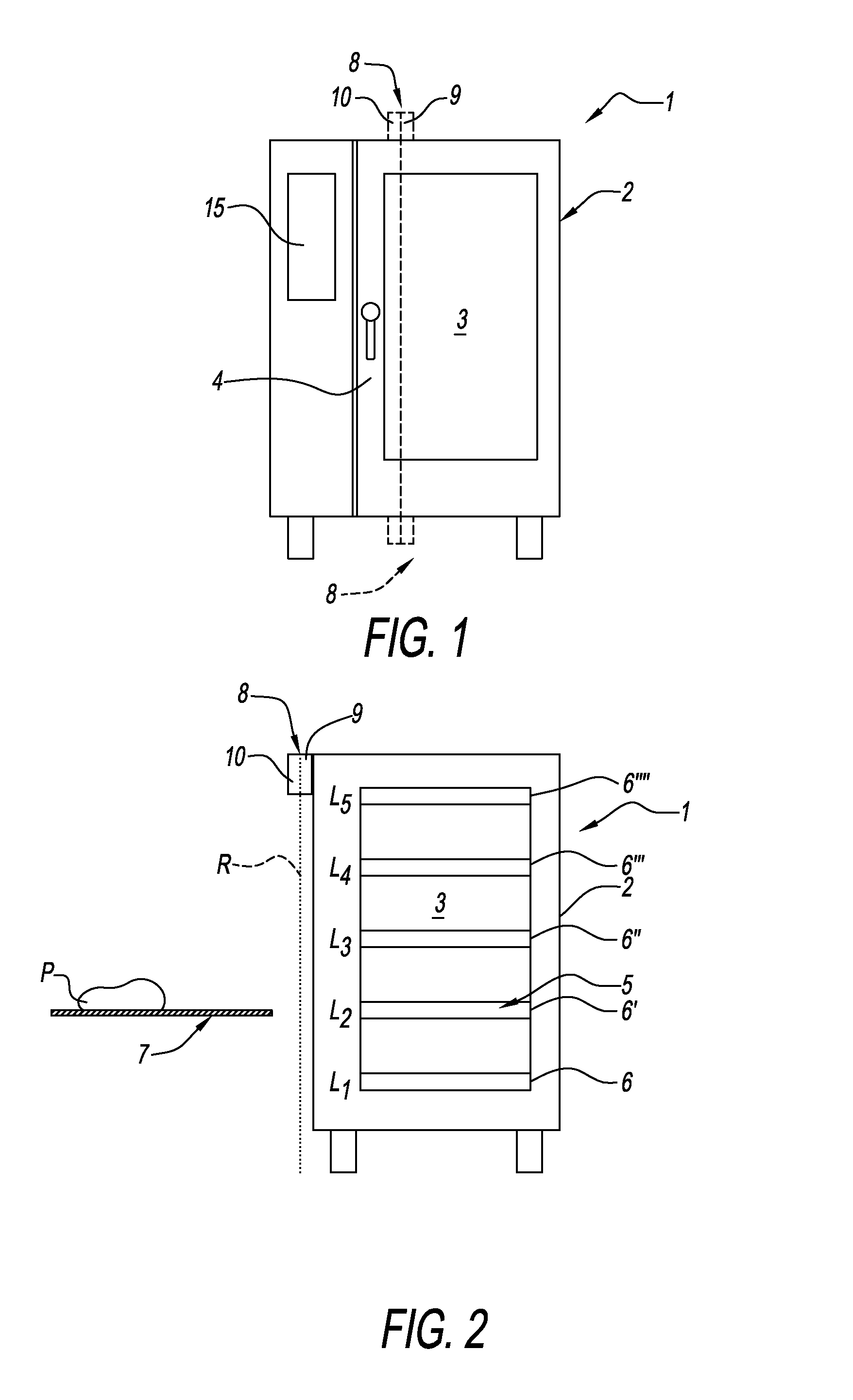
[0048]FIG. 1 shows a front view of the general configuration of a cooking device 1 that may be employed with the inspection systems of the present disclosure. Cooking device 1 can be a cooking device for commercial use such as, e.g., a combi-steamer, a baking oven or a microwave oven. Cooking device 1 comprises a housing 2 including a cooking chamber 3 that accessed by opening and closing a door 4. Cooking device 1 further comprises an inspection system 8 that is depicted in a highly simplified manner as two blocks; one block comprising a distance sensor 9 and the other block comprising a digital optical recognition device 10. As depicted in FIG. 1, inspection system 8 can be configured to be at or near the top of cooking device 1 near or adjacent door 4 (or alternatively at or near the bottom of cooking device 1) with distance sensor 9 and digital optical recognition device 10 in close proximity to each other. Cooking device 1 also includes a user interface 15.

[0049]As shown in FIG...


PUM


Abstract

Disclosed are cooking devices having inspection systems including: a distance sensor and a digital optical recognition device. The distance sensor detects the position of the food product placed in the cooking device and the digital optical recognition device captures a series of images for the purpose of food product recognition. Once the food product is recognized, the operator is provided with the correct cooking cycle / program for the position and type of food product placed in the cooking device. The inspection systems also ensure that the food product has been properly cooked at the end of the cooking cycle / program. The inspection systems ensure: (1) the food product is correctly recognized; (2) the cooking cycle / program is correctly selected; (3) the correct cooking cycle / program is followed to completion and (4) the quality of the cooked food product meets expected standards.

Description

CROSS-REFERENCED APPLICATIONS[0001]This application is related, and claims priority, to U.S. Provisional Application Nos. 61 / 604,805 and 61 / 644,820, both filed on May 9, 2012, that are incorporated herein in their entirety by reference thereto.BACKGROUND[0002]1. Field of the Disclosure[0003]The present disclosure relates to cooking devices and methods of operating such cooking devices. In particular, the present disclosure relates to cooking devices for commercial use, especially a combi-steamer, a baking oven or a microwave oven, that include inspection systems and methods for ensuring that the food product to be cooked in the cooking device is cooked according to the proper cooking cycle / program for the type and placement of food product in the cooking device. Also, the present disclosure relates to inspection systems and methods that determine whether the cooked food product has been cooked properly and meets appropriate standards for the cooked food product.[0004]2. Background o...

Claims


Application Information

Patent Timeline
Patent Type & Authority Applications(United States)
IPC IPC(8): A47J36/00G06K9/62
CPCA47J36/00G06K9/6201F24C7/085H05B6/6435H05B6/687H05B6/6447G06F18/22H04N25/00A23L5/10A23V2002/00G06T7/001G06T2207/30128H05B6/6455
Inventor RIEFENSTEIN, LUTZ
Owner WELBILT DEUT GMBH
Why Eureka
Try Eureka