
Drive control apparatus and control method for hybrid vehicles and hybrid vehicle

a hybrid vehicle and control apparatus technology, applied in vehicle position/course/altitude control, process and machine control, instruments, etc., can solve the problems of failure to produce any torque value matching the command torque, failure to control in the driving system, and extremely limited torque produced, so as to facilitate the control of the engine rotation speed, prevent the effect of the motor generator

Active Publication Date: 2013-11-14
SUZUKI MOTOR CORP
View PDF2 Cites 10 Cited by
  • Summary
  • Abstract
  • Description
  • Claims
  • Application Information

AI Technical Summary

Benefits of technology

This patent text describes a drive control system for hybrid vehicles. The system uses a torque command value and the permissible output torque of a motor generator to control the engine's rotation speed. By correcting the target engine torque based on these values, the system prevents the motor generator from over-speeding and ensures a stable driving system. This allows for better control and prevents unstable driving. Overall, the system integrates the engine and the motor generator to achieve efficient and stable driving.

Problems solved by technology

However, if the motor generator is given a command for an absolute value of torque to be larger than the absolute value of its permissible output torque, it fails to produce any value of torque matching the command torque.
There is torque produced at the motor generator, which is limited to the permissible output torque or smaller, so the produced torque becomes extremely limited as the permissible output torque gets smaller in the absolute value, approaching a zero.
Such being the case, there were situations involving a motor generator failing to produce necessary torque, causing a failed control in a driving system including the motor generator, as an inconvenience constituting an obstacle to the running of a vehicle.

Method used


Image

  • Drive control apparatus and control method for hybrid vehicles and hybrid vehicle
  • Drive control apparatus and control method for hybrid vehicles and hybrid vehicle
  • Drive control apparatus and control method for hybrid vehicles and hybrid vehicle

Examples


Embodiment Construction

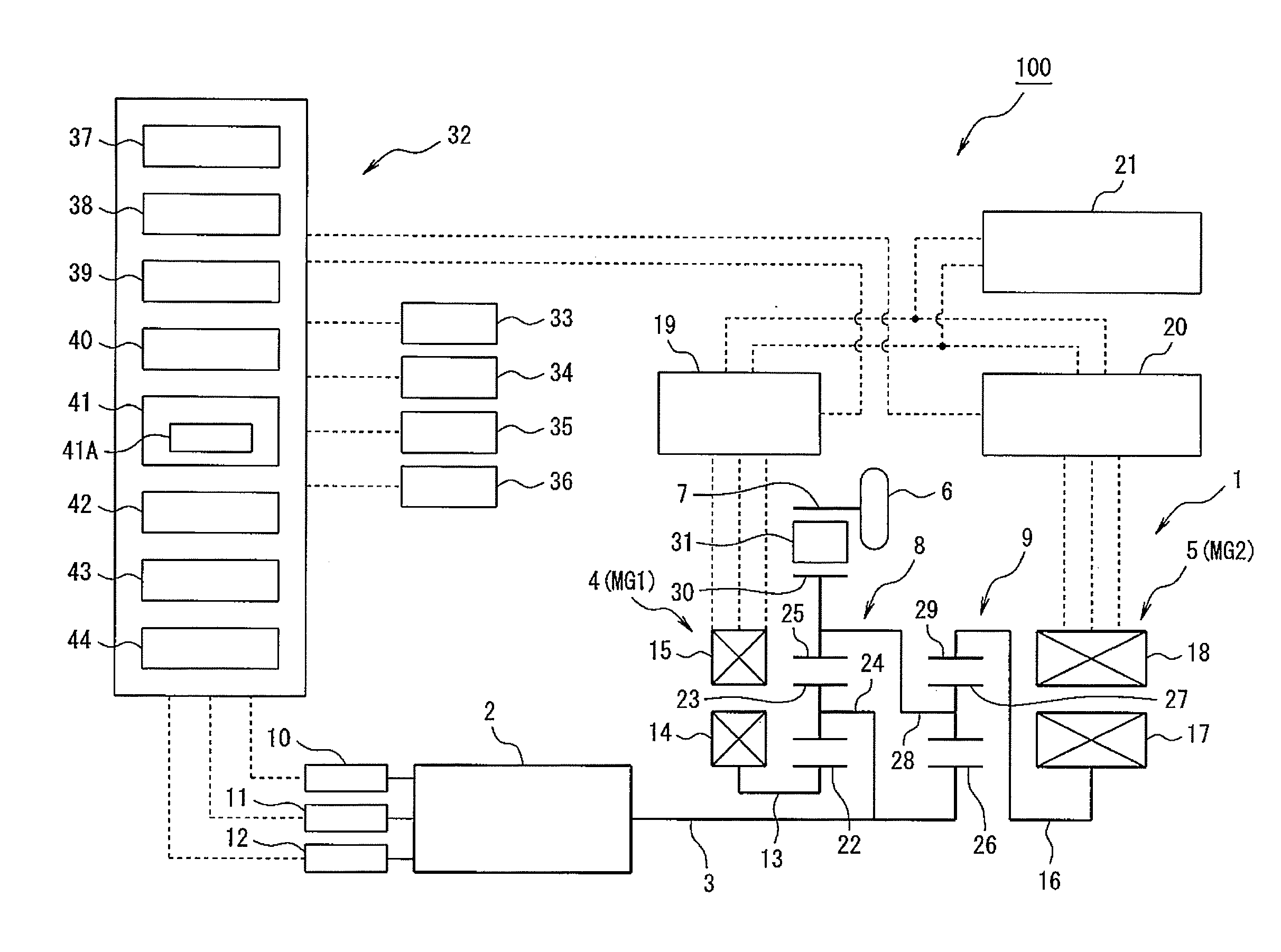
[0040]According to embodiments of the present invention, there is provided a hybrid vehicle adapted to travel using outputs from an internal combustion engine and a motor generator, under a drive control. The hybrid vehicle has mounted thereon a drive control apparatus including a target engine operating point setter, and a motor torque command value calculator. The target engine operating point setter is made to set up a target engine operating point for use to determine a target engine rotation speed and target engine torque of the internal combustion engine based on an efficiency of the system entirety and target engine power. The motor torque command value calculator works for paired motor generators, as an implement for setting respective torque command values thereto. The drive control apparatus mounted on the hybrid vehicle is made up to control the target engine torque, to decrease the torque by a correction thereto using a target engine torque correction value it has set up...


PUM


Abstract

A drive control apparatus for hybrid vehicles adapted to facilitate controlling a rotation speed of an internal combustion engine, preventing excess speeds of a motor generator. The drive control apparatus for hybrid vehicles is adapted for a drive control of a vehicle using outputs from an engine and motor generators, and includes a target engine operating point setter for setting up a target engine operating point to determine target engine torque and a target engine rotation speed of the engine from target engine power and an efficiency of system. A motor torque command value calculator sets up respective torque command values of the motor generators, and an engine torque corrector corrects the target engine torque by a target engine torque correction value set up based on the torque command values of the motor generators and permissible output torque of the motor generators.

Description

TECHNICAL FIELD[0001]The present invention relates to drive control technologies for hybrid vehicles affording to prevent over speeds of a motor generator.BACKGROUND ART[0002]There have been proposals made for hybrid vehicles including a motor generator besides an internal combustion engine (referred herein sometimes simply as an engine) for traction use. In those hybrid vehicles, the motor generator has permissible output torque that can be output such as when driving or when generating electricity, as it is determined by inherent characteristics. The permissible output torque is substantially constant within a predetermined revolution number range (as a rotation speed range) constituting a normal service range of the motor generator.[0003]When the internal combustion engine has a varied output characteristic due to disturbances such as variations in the environment, such as those in the temperature of suction air or in the atmospheric pressure, for instance, the motor generator be...

Claims


Application Information

Patent Timeline
Patent Type & Authority Applications(United States)
IPC IPC(8): B60W20/00
CPCB60W20/108Y10S903/903B60W10/06B60W10/08B60W20/00B60W30/184B60W30/1882B60W2710/0644B60W2710/0666B60W2710/081B60W2710/083B60K6/445Y02T10/62B60L15/00B60W20/10B60W30/1884
Inventor HOSOE, YUKIHIROITO, YOSHIKITAGAWA, MASAAKIOHKUMA, HITOSHI
Owner SUZUKI MOTOR CORP
Learn More