System and method for measuring parameters of motion of a projectile as it exits the muzzle of a gun
a technology of projectiles and parameters, applied in the direction of instruments, force/torque/work measurement, explosion force measurement, etc., can solve the problems of many sources of inaccuracy in the current means for delivering mortar and artillery shells, the accuracy of the precise trajectory of the projectile cannot always be predicted to the desired degree of accuracy, and the method suffers
- Summary
- Abstract
- Description
- Claims
- Application Information
AI Technical Summary
Benefits of technology
Problems solved by technology
Method used
Image
Examples
embodiment 1000
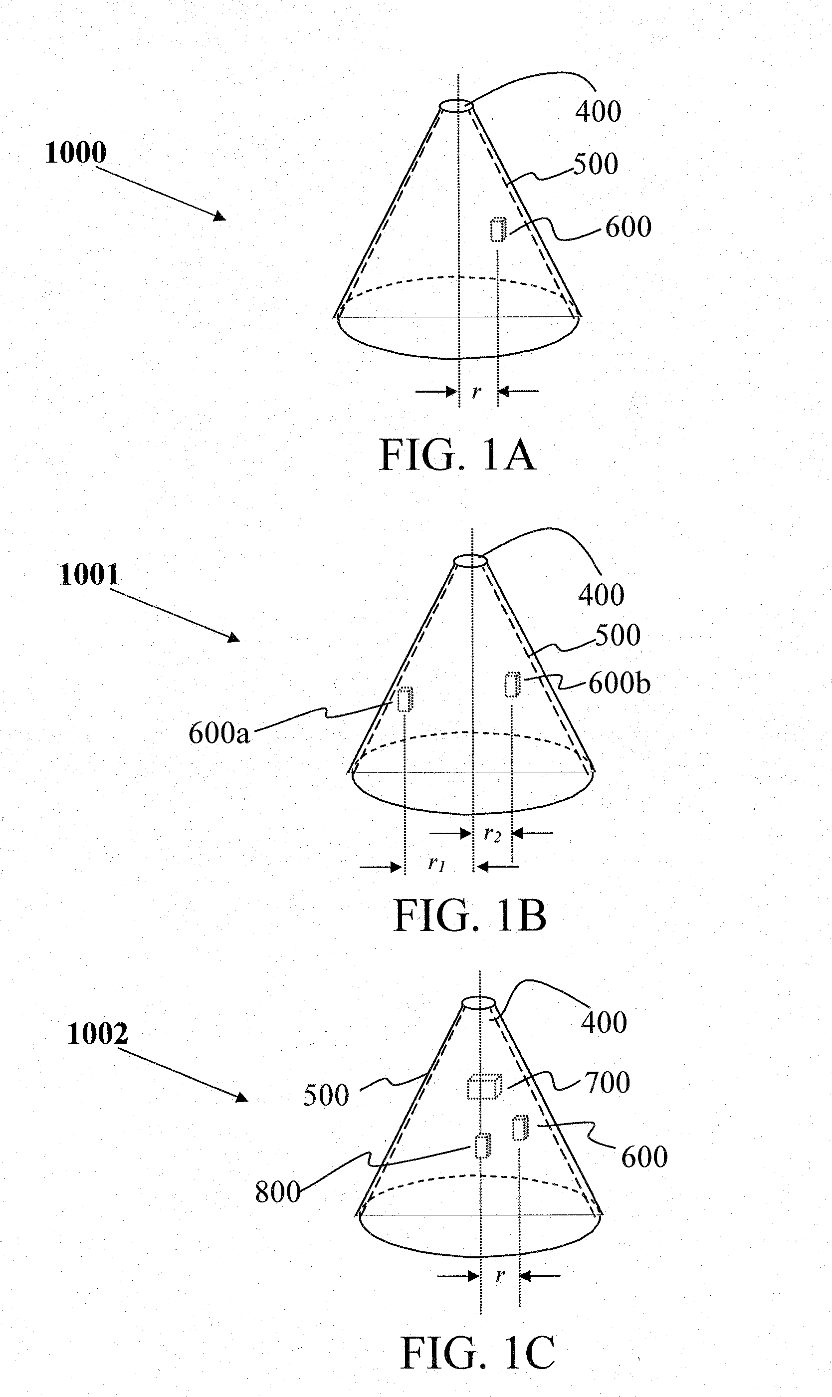
[0093]Reference is now made to FIG. 1, which presents schematic views of the onboard sensors located within projectile 400. FIG. 1A illustrates an embodiment 1000 comprising the simplest possible arrangement, in which one magnetic sensor 600 is located within the projectile, displaced from the longitudinal axis of the projectile by a distance r. The magnetic sensor may be of any type known in the art. In preferred embodiments of the invention, Anisotropic Magnetoresistive (AMR) sensors are used. In all of the embodiments illustrated in FIGS. 1A-1C, all sensors located within the projectile are in electrical connection with a control system (not shown in the figure) adapted for measurement and calculation of trajectory parameters; the control system is described in detail below. The control electronics comprise a microprocessor comprising at least a timing circuit and a logic circuit. In preferred embodiments of the invention, the microprocessor comprises or is in logical connection ...
embodiment 2000
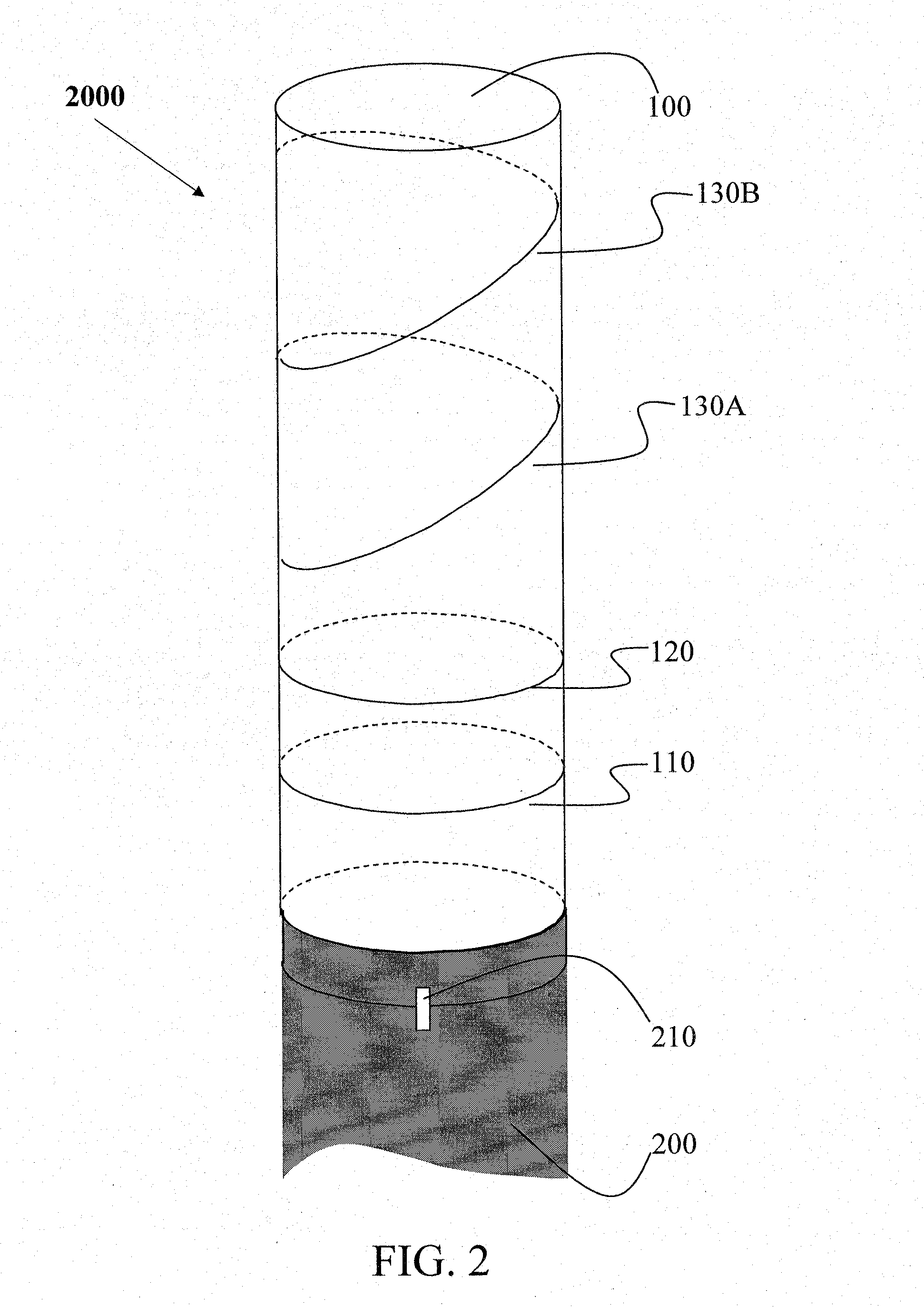
[0096]Reference is now made to FIG. 2, which presents a schematic illustration of an embodiment 2000 of the second part of the invention herein disclosed, namely, a non-magnetic sleeve (100) with magnetic components. The non-magnetic sleeve is cylindrical in shape and may be constructed of any non-magnetic material suitable for use with the particular gun and projectile being used. In preferred embodiments, the sleeve is constructed of a non-magnetic mesh. The inner diameter of non-magnetic sleeve 100 is appropriate to provide a slip fit over the muzzle of gun barrel 200. In preferred embodiments of the invention, the muzzle and the matching end of the non-magnetic sleeve are provided with means for fixing their relative orientations, e.g. by a tab-and-slot or mark arrangement 210.
[0097]The sleeve system comprises two sets of rings made of a suitable magnetic material; in preferred embodiments of the invention, the rings are constructed from magnets made of neodymium-iron-boron allo...
embodiment 3000
[0118]Reference is now made to FIG. 6, which shows an embodiment 3000 of the system that includes both a third horizontal ring 125 and the parameter entry system 140 described above. The third horizontal ring can be used to derive the linear acceleration as described above, and the parameter entry system is placed near the end of the sleeve in order to enable parameter entry after all of the measurements relevant to parameters of motion have been made.
[0119]While the main object of the invention is to provide means for determining the linear and angular muzzle velocities of a projectile in which all measurements and calculations are performed entirely onboard, it is within the scope of the invention to include embodiments that further comprise means for communicating the values obtained to a location external to the projectile. In various embodiments, the projectile itself can comprise means for transmitting the information (e.g. via a radio, microwave, or optical transmitter) to a ...
PUM
 Abstract
Description
Claims
Application Information
 - R&D
- Intellectual Property
- Life Sciences
- Materials
- Tech Scout
- Unparalleled Data Quality
- Higher Quality Content
- 60% Fewer Hallucinations
Browse by: Latest US Patents, China's latest patents, Technical Efficacy Thesaurus, Application Domain, Technology Topic, Popular Technical Reports.
© 2025 PatSnap. All rights reserved.Legal|Privacy policy|Modern Slavery Act Transparency Statement|Sitemap|About US| Contact US: help@patsnap.com


