
Gesture recognition

a gesture recognition and gesture technology, applied in the field of gesture recognition, can solve the problems of high device power consumption, complicated processing required to generate gesture control information using such techniques, and high cost of conventional gesture recognition techniques, so as to reduce complexity, reduce cost, and be simple to transmit

Inactive Publication Date: 2013-11-21
STMICROELECTRONICS (RES & DEV) LTD
View PDF18 Cites 20 Cited by
  • Summary
  • Abstract
  • Description
  • Claims
  • Application Information

AI Technical Summary

Benefits of technology

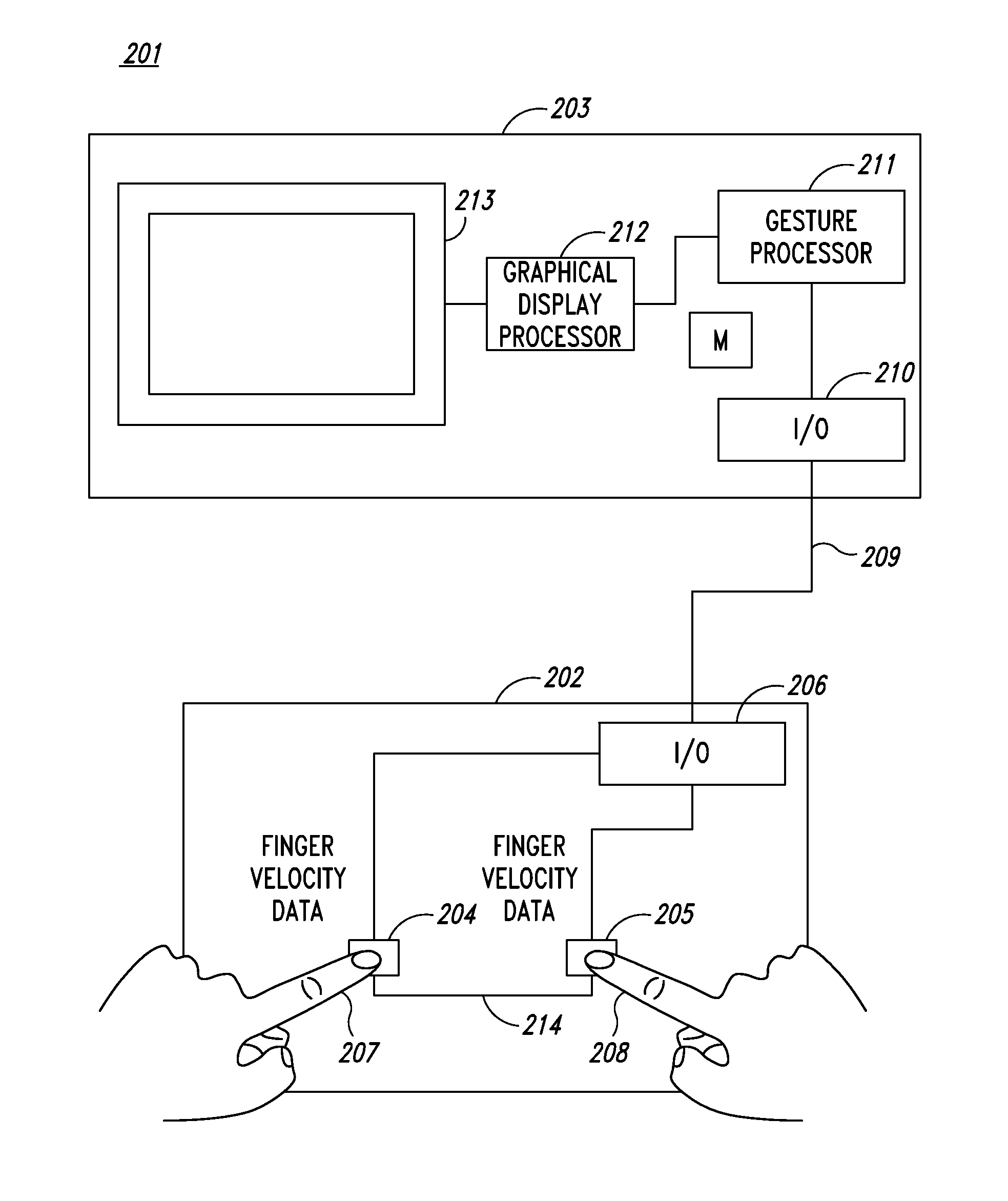
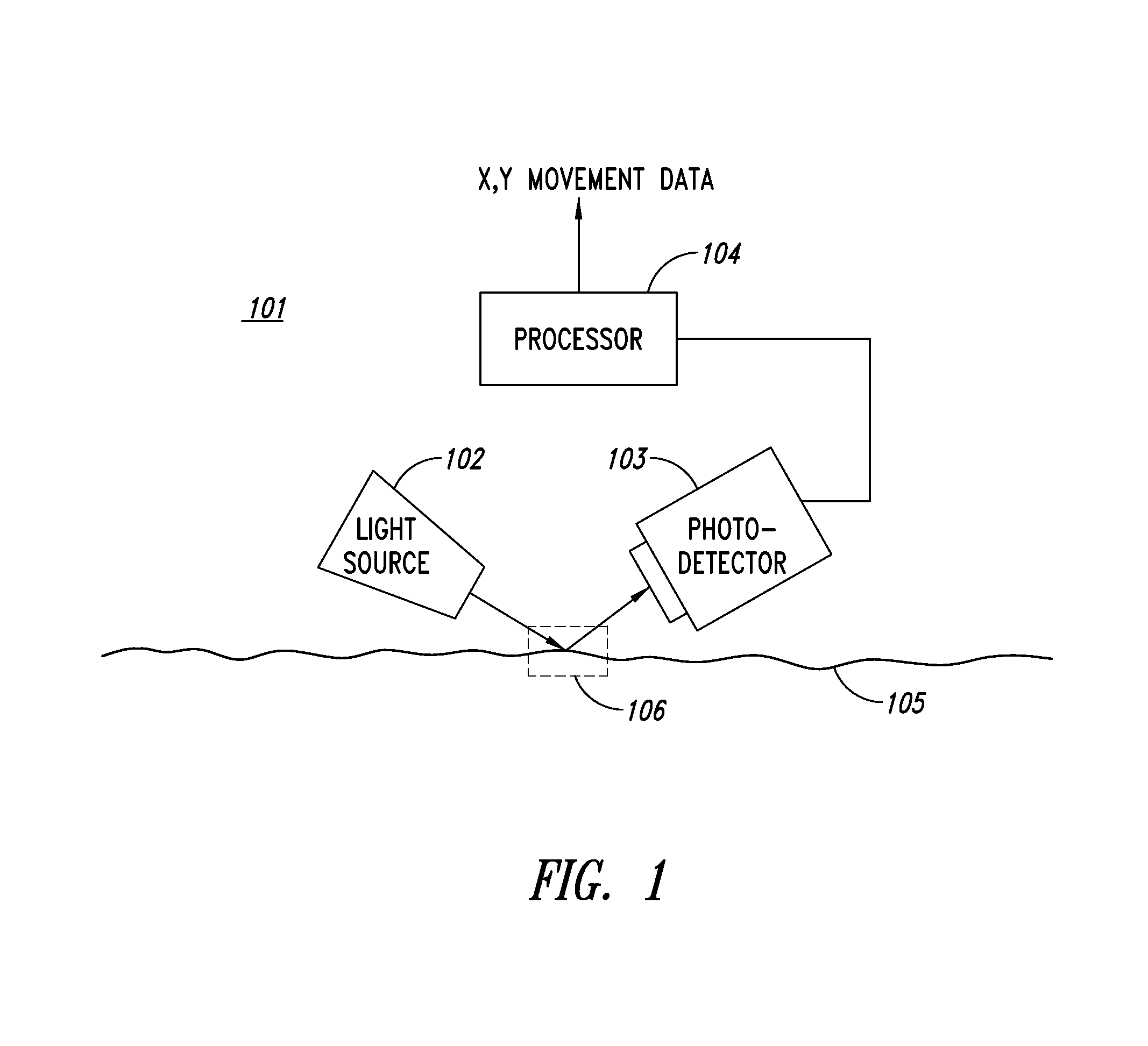
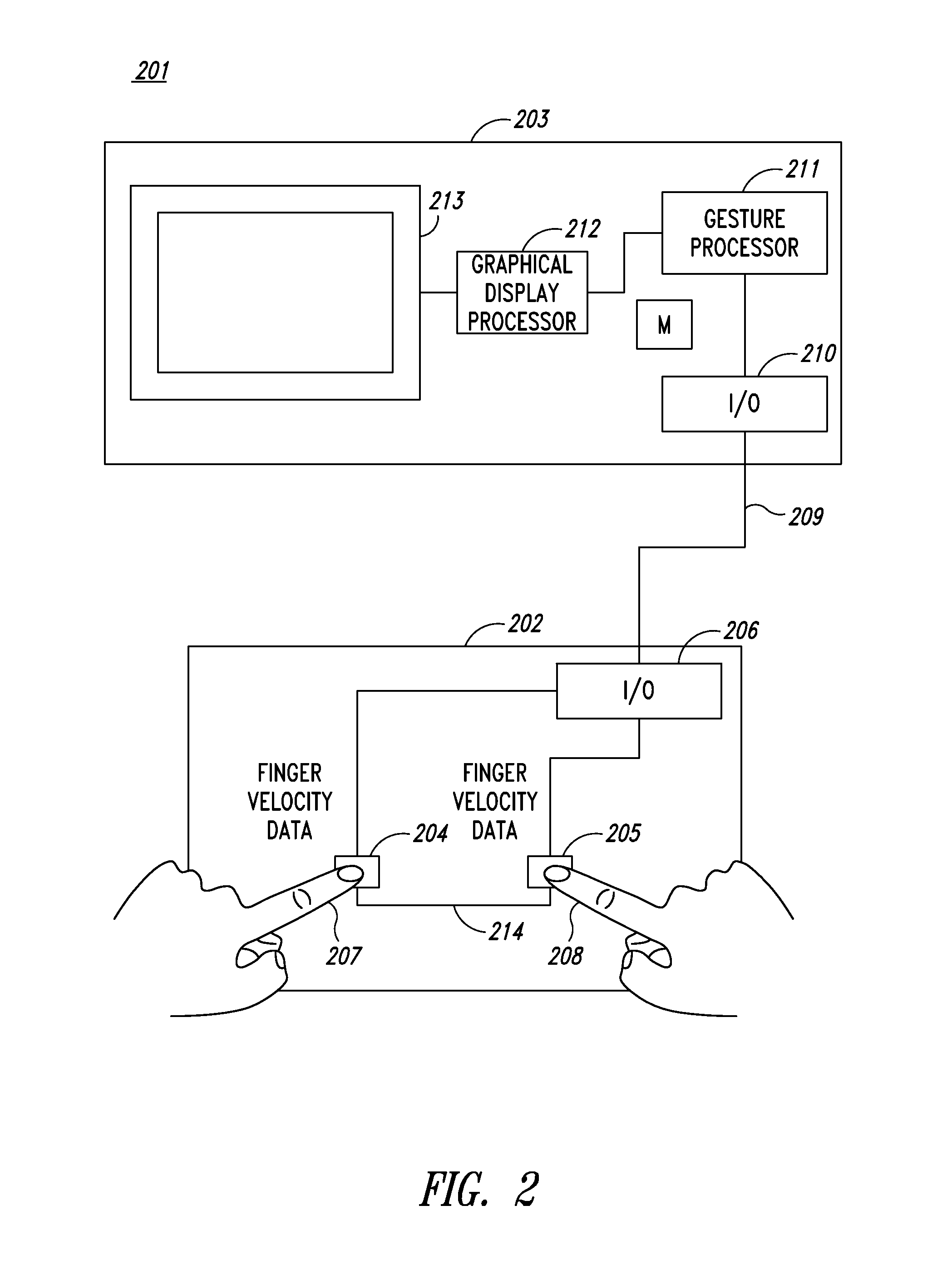
The invention provides a better way to recognize gestures using a user input device with multiple optical sensors. This method is cheaper and simpler than traditional techniques and can be used in low-cost peripheral devices like keyboards. The optical sensors capture information about the velocity of the user's parts relative to the sensors, so there is no need to track their position over time. This makes it easier to control the device using gestures.

Problems solved by technology

The processing required to generate gesture control information using such techniques is complicated.
This is particularly difficult in “multi-touch” implementations where the user uses two or more contact points to input gestures.
Furthermore, touch sensitive surfaces such as capacitive touch screens and touch pads that are required to implement conventional gesture recognition techniques are expensive and consume a lot of device power during operation and are therefore unsuitable for many applications that would otherwise benefit from being enabled to receive gesture control input.

Method used


Image

  • Gesture recognition
  • Gesture recognition
  • Gesture recognition

Examples


example implementation

[0089]FIG. 6 provides a schematic diagram illustrating an implementation of a system 600 arranged in accordance with an example embodiment. The system includes a keyboard based user input device 601 connected via a universal serial bus (USB) interface to a personal computer (PC) computing device 602. As illustrated, the PC 602 employs the Windows® operating system. Other operating systems may be employed. The keyboard based user input device 601 includes a keyboard unit 603 and an optical sensor unit 604 including a first optical sensor 605 and a second optical sensor 606. Each optical sensor includes a photo-diode 607 and a sensor movement processor 610, which may be, for example, based on a STMicroelectronics VD5376 motion sensor device. It will be understood that other movement processors can be used, such as a STMicroelectronics VD5377 motion sensor device.

[0090]The first and second optical sensors 605, 606 are connected to a movement processor 609 via a MOTION line (MOTIONL for...


PUM


Abstract

A system includes two or more optical sensors configured to generate image data based on gestures made by a user. One or more processing devices identifies movement quadrants based on the generated image data. If a match of the identified movement quadrants to one of a set of gesture commands is detected, one or more control signals associated with the matching gesture command are generated.

Description

BACKGROUND[0001]1. Technical Field[0002]The present disclosure relates to systems, devices and methods for gesture recognition, and in particular for receiving gesture input from a user.[0003]2. Description of the Related Art[0004]The use of positioning devices such as mice, tracker balls, and touch pads and so on to allow a user to control the position of a cursor or suchlike on a display screen has been known for many years. However, more recently gesture based control techniques have been developed that seek to go beyond simple cursor control by enabling devices to recognize particular “gestures” input by a user. Such gestures have certain control actions associated with them. For example, a “pinch” gesture may be used for zoom out, a “spread” gesture may be used for zoom in, and a “sweep” gesture may used to scroll and so on.[0005]Gesture based control is used to allow users to interact with computing devices such as smart-phones, tablet computers, portable personal computers an...

Claims


Application Information

Patent Timeline
Patent Type & Authority Applications(United States)
IPC IPC(8): G06F3/01G06F3/02
CPCG06F3/017G06F3/0202G06F3/021G06F3/0317G06F3/038G06F1/169G06F3/005G06F3/0213
Inventor RAYNOR, JEFFREY M.
Owner STMICROELECTRONICS (RES & DEV) LTD
Learn More