Regenerative Mode Locked Laser Swept Source for OCT Medical Imaging

a laser swept source and oct technology, applied in the field of oct medical imaging swept laser swept source in regenerative mode, can solve the problems of oct system spectral spacing problems, and the spectral spacing of the longitudinal cavity modes of the laser, so as to stabilize the pulsation behavior of the laser, avoid noise disruption, and stabilize the emission characteristics of the laser

Active Publication Date: 2013-11-21
EXCELITAS TECH
View PDF9 Cites 17 Cited by
  • Summary
  • Abstract
  • Description
  • Claims
  • Application Information

AI Technical Summary

Benefits of technology

[0011]The present invention concerns a swept tunable laser source. During its swept operation, it is constrained to operate in a controlled mode locked regime by using the time-varying intensity of the swept optical signal as feedback to control the mode-locked operation of laser swept source. In the illustrated embodiments, this is accomplished by actively modulating cavity gain and/or intracavity elements. This has the effect of stabilizing the emission characteristics of the laser and avoids noisy disruptions due to uncertainty or flips in the number of pulses circulating in the cavity. Instead, the mode locking system stabilizes the pulsation behavior of the laser by modulating a gain, for example, of the cavity of t

Problems solved by technology

Certain tradeoffs in laser design, however, can be problematic for OCT systems.
Short laser cavities, however, create problems in terms of the spectral spacing of the longitudinal cavity modes of the laser.
This results in greater mode hopping noi

Method used


Image

  • Regenerative Mode Locked Laser Swept Source for OCT Medical Imaging
  • Regenerative Mode Locked Laser Swept Source for OCT Medical Imaging
  • Regenerative Mode Locked Laser Swept Source for OCT Medical Imaging

Examples


second embodiment

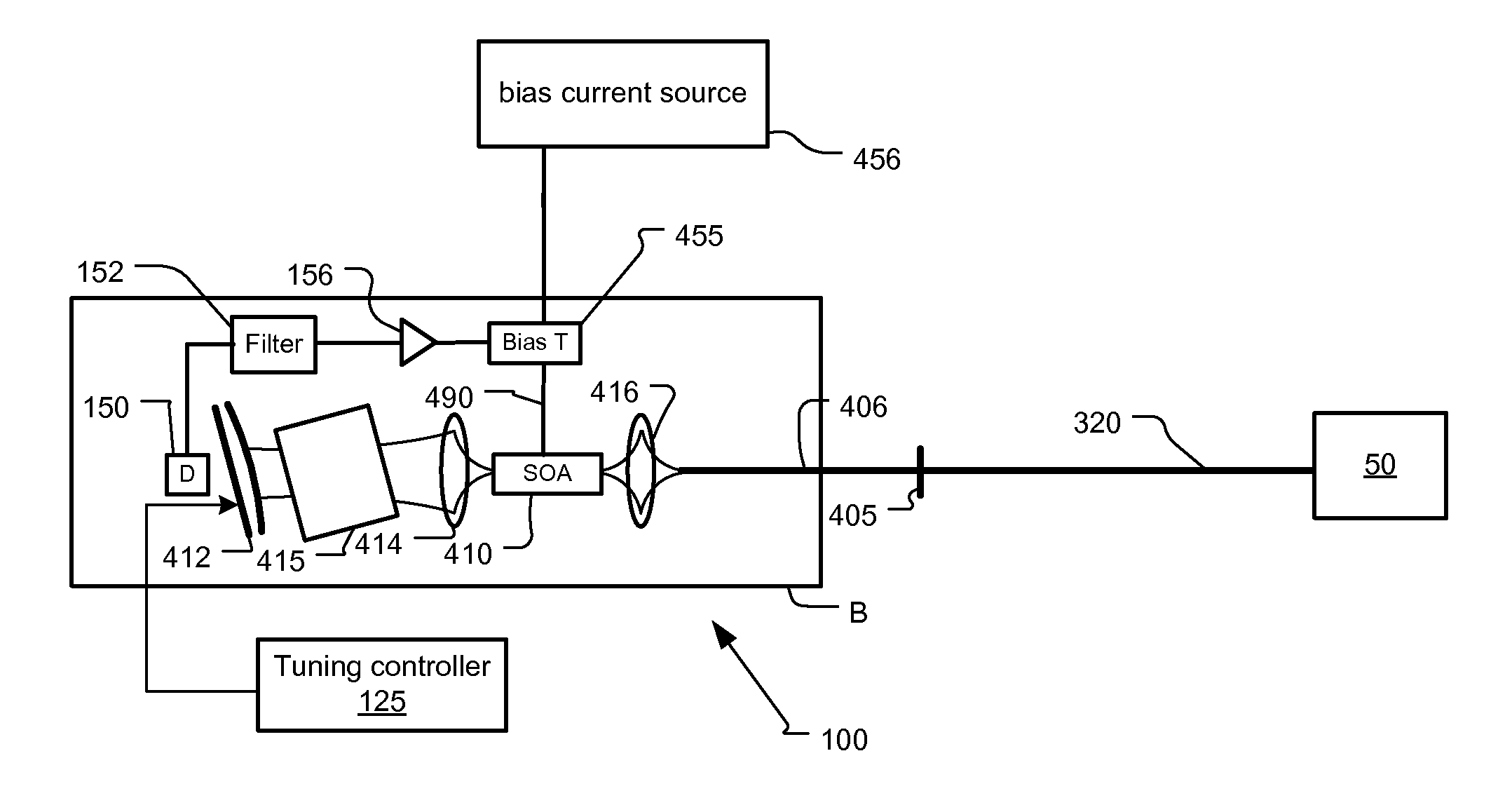
[0078]FIG. 7 illustrates a second embodiment in which the regenerative mode locking system is implemented on the optical bench B with the components of the laser 100. In this example, the electronic delay in regenerative feedback path is kept small. This reduces or even eliminates the need for the electronic delay 154 in some examples.

third embodiment

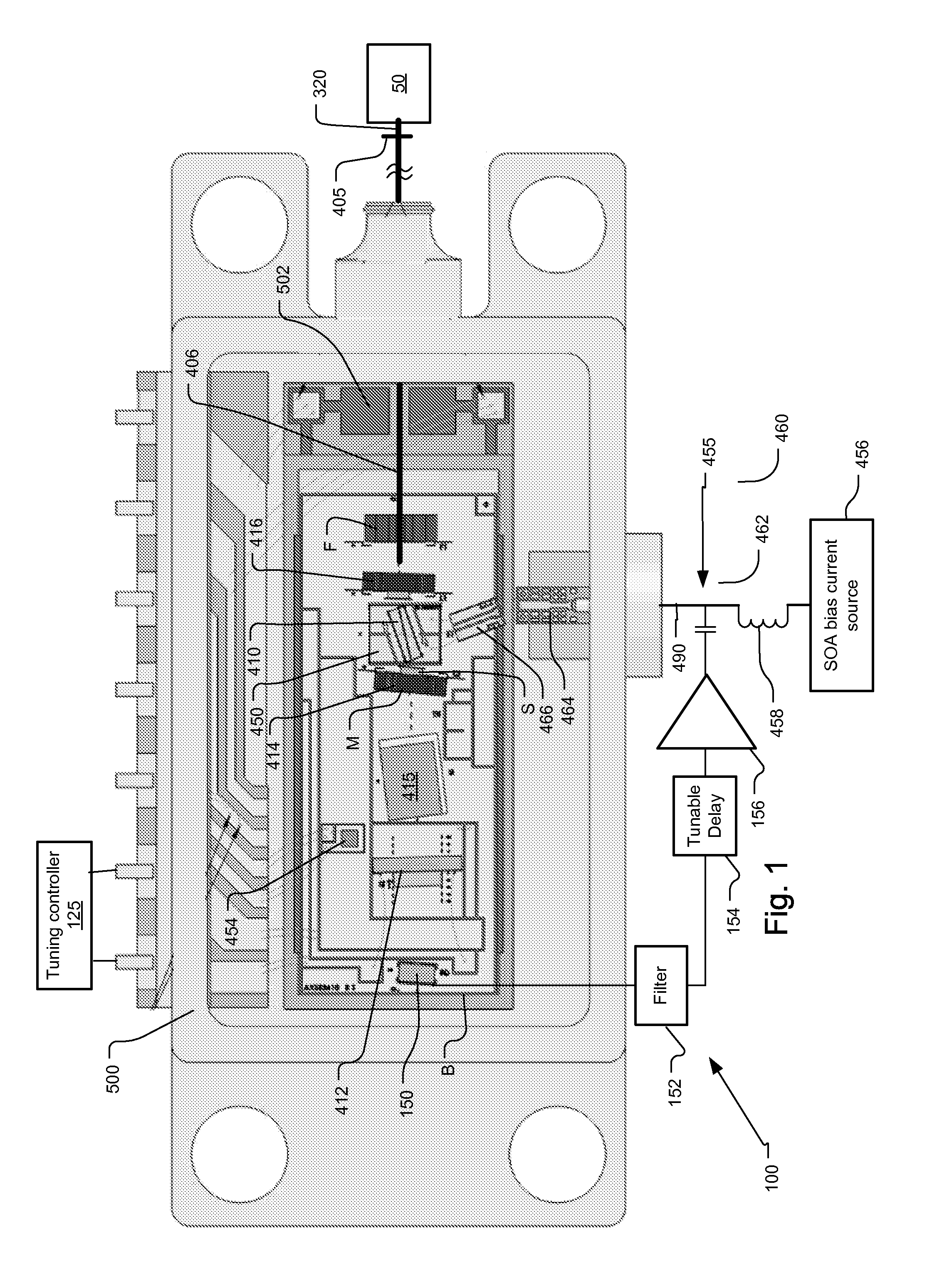
[0079]FIG. 8 illustrates a third embodiment in which the regenerative feedback system modulates a phase and / or gain / loss of the optical signals circulating in the laser cavity. In more detail, a phase modulator 470 is added into the cavity, preferably towards one end of the cavity to control the mode locked operation of the laser. In one embodiment, the phase modulator 470 is installed on the bench B between the SOA 410 and the lens structure 416. In the preferred embodiment, it is a semiconductor chip that is integral with the SOA chip 410 and specifically a phase modulation section to which a separate, modulated bias current or Voltage is supplied to thereby yield a two-section SOA (gain, phase). Integrated phase modulators generally work forward biased through current injection, but reverse biased types also exist.

[0080]In other examples, the phase modulator 470 is an external modulator, such as LiNbO3.

[0081]Preferably, the modulation to the phase modulator 470 is generated as de...


PUM


Abstract

An optical coherence analysis system uses a laser swept source that is constrained to operate in a mode locked condition using regenerative mode-locking This is accomplished by synchronously changing the laser cavity's net gain and/or phase based on time varying intensity of the swept optical signal generated by the laser. This produces a stable pulsation behavior, which is associated with smooth tuning (low optical frequency reference clock jitter) and low relative intensity noise (RIN).

Description

BACKGROUND OF THE INVENTION[0001]Optical coherence analysis relies on the use of the interference phenomena between a reference wave and an experimental wave or between two parts of an experimental wave to measure distances and thicknesses, and calculate indices of refraction of a sample. Optical Coherence Tomography (OCT) is one example technology that is used to perform high-resolution cross sectional imaging. It is often applied to imaging biological tissue structures, for example, on microscopic scales in real time. Optical waves are reflected from an object or sample and a computer produces images of cross sections of the object by using information on how the waves are changed upon reflection.[0002]Fourier domain OCT (FD-OCT) currently offers the best performance for many applications. Moreover, of the Fourier domain approaches, swept-source OCT has distinct advantages over techniques such as spectrum-encoded OCT because it has the capability of balanced and polarization diver...

Claims


Application Information

Patent Timeline
IPC IPC(8): G01B9/02
CPCA61B5/0066G01B9/02004G01B9/02091G01N21/4795H01S5/02216H01S5/02415H01S5/0657H01S5/0683H01S5/142H01S5/02251H01S5/02325
Inventor KUZNETSOV, MARK E.JOHNSON, BARTLEY C.
Owner EXCELITAS TECH
Why Eureka
Try Eureka