Laser Swept Source with Controlled Mode Locking for OCT Medical Imaging

a technology of controlled mode and swept source, which is applied in the field of laser swept source with controlled mode locking for oct medical imaging, can solve the problems of lasers that cannot produce light at integer multiples of cavity modes, can only design certain tradeoffs, and can be problematic for oct systems, so as to facilitate high-speed tuning and facilitate the effect of tuning

Active Publication Date: 2014-03-27
EXCELITAS TECH
View PDF7 Cites 7 Cited by
  • Summary
  • Abstract
  • Description
  • Claims
  • Application Information

AI Technical Summary

Benefits of technology

[0009]Research with tunable lasers has shown that when they are operated at high swept rates they tend to operate in a mode locked regime. At high sweep rates, one or more pulses travel in the laser cavity as is found in a traditional mode locked laser. The pulse repetition rate is close to the laser cavity roundtrip time or to a typically small, say a factor of 2 to 10, multiple. Since this mode locking rises from frequency tuning of the laser, it is termed swept mode locking This mode locked regime can have the effect of actually facilitating the high-speed tuning of the laser. A four-wave mixing effect red shifts the wave in the laser cavity. This facilitates the tuning to lower optical frequencies. See A. Bilenca, S. H. Yun, G. J. Tearney, and B. E. Bouma, “Numerical study of wavelength-swept semiconductor ring lasers: the role of refractive-index nonlinearities in semiconductor optical amplifiers and implications for biomedical imaging applications”, OPTICS LETTERS / Vol. 31, No. 6 / Mar. 15, 2006.

Problems solved by technology

Certain tradeoffs in laser design, however, can be problematic for OCT systems.
Short laser cavities, however, create problems in terms of the spectral spacing of the longitudinal cavity modes of the laser.
That is, lasers can only produce light at integer multiples of the cavity mode spacing since the light must oscillate within the cavities.
This results in greater mode hopping noise as the laser is tuned over these discrete cavity modes.
The drawback of these devices is their complexity, however.
Moreover, the ring cavity including the long storage fiber creates its own performance problems such as dispersion and stability.

Method used


Image

  • Laser Swept Source with Controlled Mode Locking for OCT Medical Imaging
  • Laser Swept Source with Controlled Mode Locking for OCT Medical Imaging
  • Laser Swept Source with Controlled Mode Locking for OCT Medical Imaging

Examples


Embodiment Construction

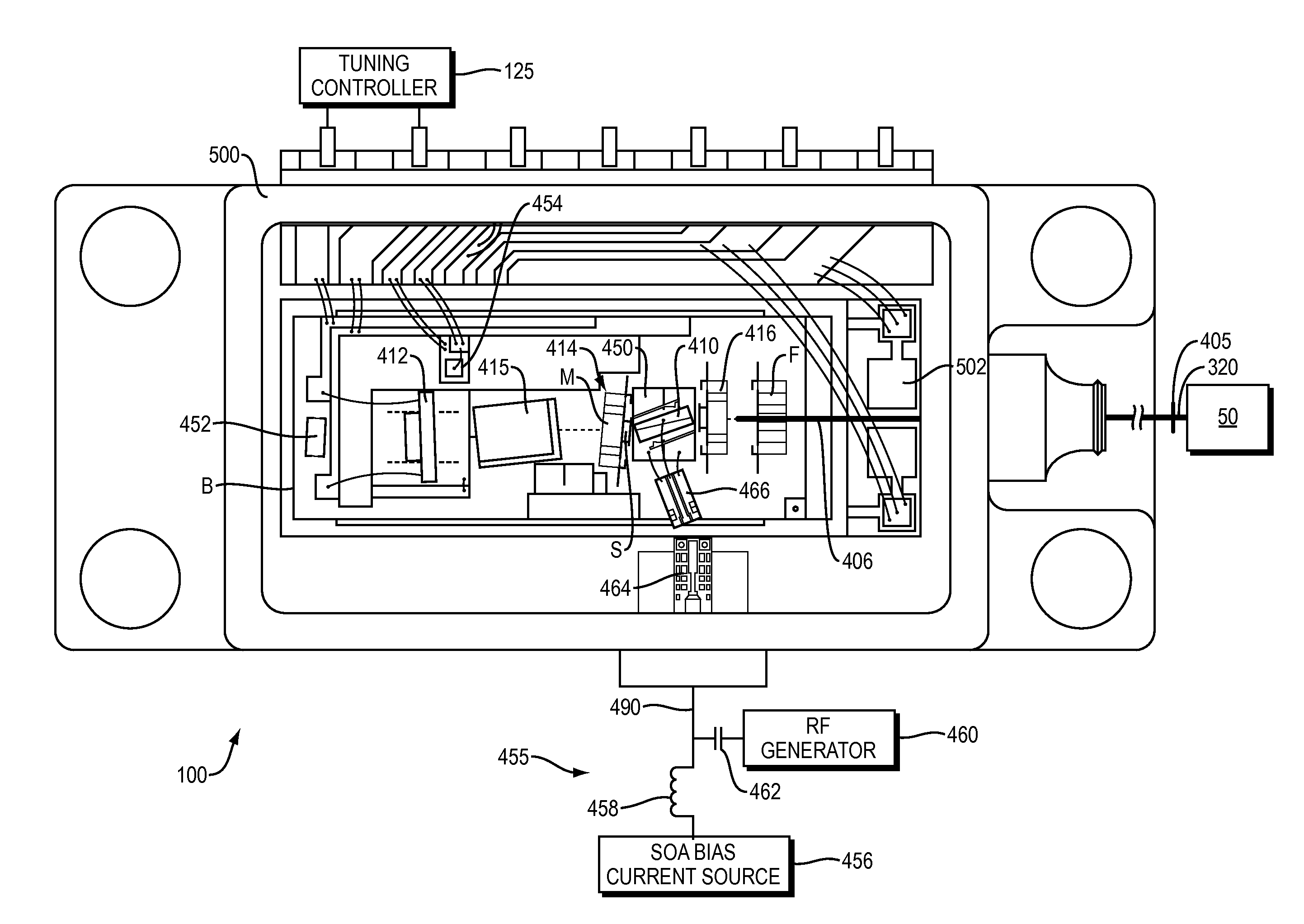
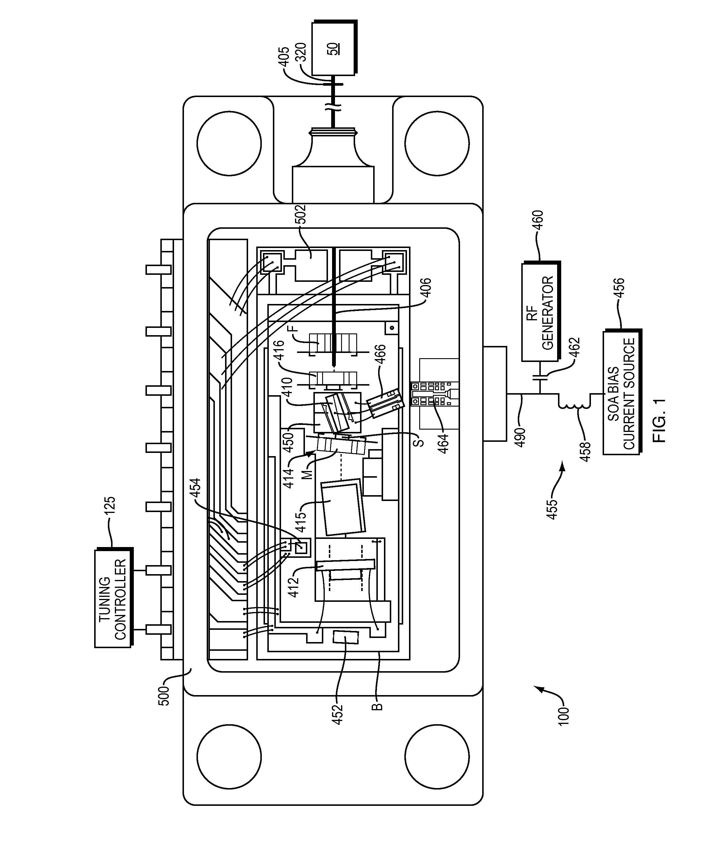
[0045]FIG. 1 shows mode-locked laser swept source 100 for optical coherence analysis, which has been constructed according to the principles of the present invention. This embodiment controls or stabilizes the mode-locked operation by modulating the bias current to an intracavity gain element.

[0046]In the current embodiment, the laser swept source 100 is preferably a laser as generally described in incorporated U.S. Pat. No. 7,415,049 B1. It includes a linear cavity with a gain element 410 and a frequency tuning element 412. In the illustrated example, the frequency tuning element is a Fabry-Perot filter, which defines one end of the cavity, in the illustrated implementation.

[0047]In other embodiments, other cavity configurations are used such as ring cavities. Further other cavity tuning elements are used such as gratings and thin-film filters. These elements can also be located entirely within the cavity such as an angle isolated Fabry-Perot tunable filter or grating.

[0048]Current...


PUM


Abstract

An optical coherence analysis system uses a laser swept source that is constrained to operate in a mode locked condition. This is accomplished by synchronously changing the laser cavity's gain and/or phase based on the round trip travel time of light in the cavity. Many high-speed wavelength swept laser sources emit pulses synchronized with the round trip time of the cavity as part of a nonlinear optical frequency red shifting process. Stable pulsation is associated with smooth tuning and low relative intensity noise. Addition of mode-locking methods to this class of lasers can control and stabilize these lasers to a low clock jitter and RIN state, and in specific cases allow long-to-short wavelength tuning in addition to the usual short-to-long (red shifting). The laser may comprise a SOA (410), a tunable Fabry-Perot-Filter (412) as one reflector and an Output coupler (405) in an optical fiber (406) to adjust the cavity length.

Description

RELATED APPLICATIONS[0001]This application claims priority to U.S. patent application Ser. No. 12 / 979,225, filed on Dec. 27, 2010, which is incorporated herein by reference in its entirety.BACKGROUND OF THE INVENTION[0002]Optical coherence analysis relies on the use of the interference phenomena between a reference wave and an experimental wave or between two parts of an experimental wave to measure distances and thicknesses, and calculate indices of refraction of a sample. Optical Coherence Tomography (OCT) is one example technology that is used to perform high-resolution cross sectional imaging. It is often applied to imaging biological tissue structures, for example, on microscopic scales in real time. Optical waves are reflected from an object or sample and a computer produces images of cross sections of the object by using information on how the waves are changed upon reflection.[0003]Fourier domain OCT (FD-OCT) currently offers the best performance for many applications. Moreo...

Claims


Application Information

Patent Timeline
Patent Type & Authority Applications(United States)
IPC IPC(8): G01B9/02H01S3/11
CPCH01S3/1112G01B9/02091A61B5/0066A61B5/6852G01B9/02004G01N21/4795H01L2224/48091H01S3/06791H01S3/083H01S3/094026H01S3/1062H01S3/1109H01S3/1118H01S5/0265H01S5/041H01S5/06216H01S5/0622H01S5/0657H01S5/141H01S5/146H01S5/02251H01L2924/00014
Inventor JOHNSON, BARTLEY C.FLANDERS, DALE C.
Owner EXCELITAS TECH
Why Eureka
Try Eureka