X-ray ct device

a ct scanner and x-ray technology, applied in the field of medical xray ct scanners, can solve the problems of ineffective radiation exposure of test subjects, deteriorating image quality, and difficulty in bringing cardiac beats into sync with the movement of test subjects, and achieves the effects of enhancing examination throughput, reducing imaging preparation time upon changing the fov size, and high precision of ct measuremen

Active Publication Date: 2013-11-21
HITACHI LTD
View PDF3 Cites 15 Cited by
  • Summary
  • Abstract
  • Description
  • Claims
  • Application Information

AI Technical Summary

Benefits of technology

[0015]Following is a brief explanation of the effect obtained by representative examples of the present invention being disclosed by the present application.
[0016]In the multi-source X-ray CT scanner having multiple X-ray sources, highly precise CT measurement is implemented as to various imaging FOV sizes, without exposing the test subject to ineffective radiation. In addition, imaging preparation time upon changing the FOV size is reduced, thereby enhancing examination throughput.

Problems solved by technology

However, upon imaging the heart that needs cardiac gating, there is a problem that it is difficult to bring cardiac beats into sync with the movement of the test subject.
In the three-dimensional CT image measured by the static scanning, there is a problem that cone-beam artifact may occur, with getting nearer both ends in the rotation axis direction, and therefore an image quality may be deteriorated.
Therefore, there is a problem that the test subject may be exposed to ineffective radiation.
It is to be noted that in this example, since the focal positions of the two X-ray sources are arranged at an identical point in the rotation axis direction, it is not possible to obtain an effect to reduce the cone beam artifact simultaneously with preventing occurrence of exposure to ineffective radiation in the static scanning.

Method used


Image

  • X-ray ct device
  • X-ray ct device
  • X-ray ct device

Examples


first embodiment

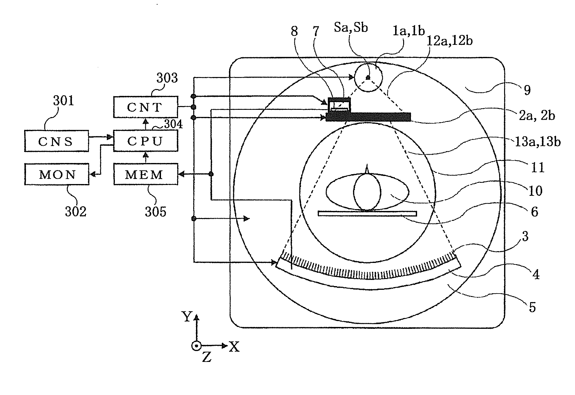
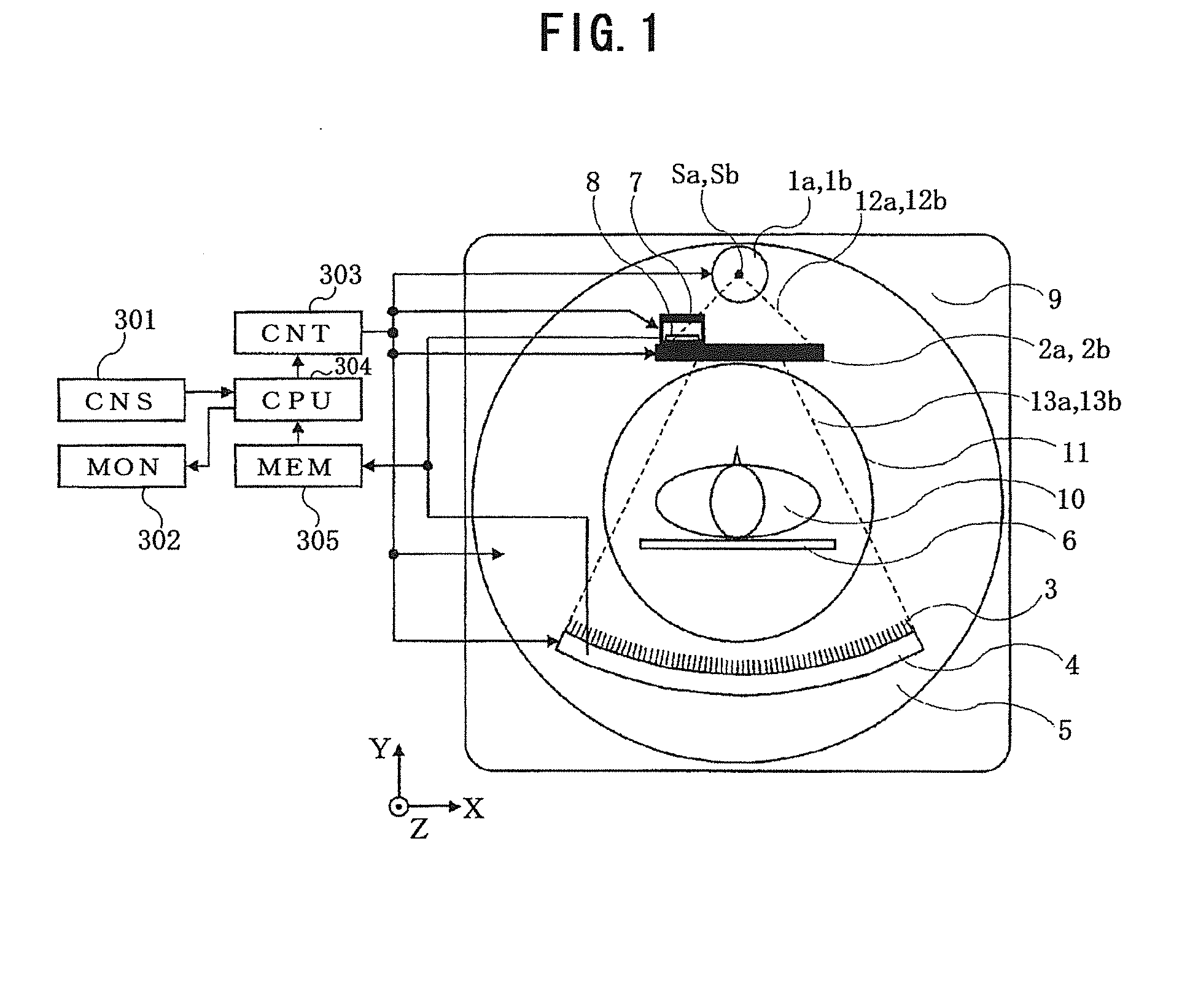
[0046]FIG. 1 is a front schematic view of the X-ray CT scanner relating to the first embodiment of the present invention. It is to be noted here that in FIG. 1, the left-right direction, the upper-lower direction, and the vertical direction on paper, are respectively assumed as X, Y and Z directions. The X-ray CT scanner relating to the first embodiment is made up of X-ray tubes 1a and 1b, collimators 2a and 2b, an anti-scatter collimator 3, an X-ray detector 4, a rotating plate 5, abed board 6, a slit 7, an auxiliary X-ray detector 8, a gantry 9, a console (CNS) 301, a monitor (MON) 302, a controller (CNT) 303, a computer (CPU) 304, a memory (MEM) 305, and the like. The X-ray tubes 1a and 1b are installed on the rotating plate 5, in such a manner that the X-ray focuses Sa and Sb of the respective X-ray tubes are located on an identical position in the XY direction, and they are positioned at different points in the Z direction. There are also installed on the rotating plate 5, in a...

second embodiment

[0109]Since a major configuration of the X-ray CT scanner relating to the second embodiment is the same as the first embodiment, the X-ray CT scanner relating to the second embodiment will be explained, focusing on different points.

[0110]FIG. 24 is a front schematic view of the X-ray CT scanner relating to a second embodiment of the present invention. Since the major configuration of the X-ray CT scanner is identical to the X-ray CT scanner as shown in FIG. 1 in the first embodiment, tedious explanations will not be made. A different point is that the slit 7 and the auxiliary X-ray detector 8 do not exist for the present X-ray CT scanner, which are used to measure position displacement in the Z direction of the X-ray focuses Sa and Sb. In the present X-ray CT scanner, instead of tolerating the displacements in the Z direction of the X-ray focuses Sa and Sb, the positions of the collimators 2a and 2b are modified, thereby keeping the X-ray irradiation region 13 to be a constant posit...


PUM


Abstract

In a multi-source X-ray CT scanner having multiple X-ray sources, an imaging FOV size is fixed. In the X-ray CT scanner, a position of at least one of multiple X-ray generators is movable in the Z-axis direction (in the rotation axis direction). It is further possible to configure such that while shifting the X-ray generator, the rotation speed of the rotating plate is kept to be a predetermined value or less. Highly precise CT measurement is implemented as to various imaging FOV sizes, without exposing the test subject to ineffective radiation.

Description

TECHNICAL FIELD[0001]The present invention relates to a medical X-ray CT scanner, and more particularly, it relates to a technique which changes an imaging field of view at high speed and appropriately in a system using a multi-focus X-ray source, so as to reduce a possibility that a test subject is exposed to ineffective radiation, and also to enhance examination throughput.BACKGROUND ART[0002]The X-ray CT scanner is an apparatus provided with a pair of an X-ray tube and an X-ray detector arranged in a manner being opposed to each other (hereinafter, referred to as “imaging system”), placing a test subject therebetween, taking an image of transparent X-ray data of the test subject while turning the imaging system, and reconstructing a cross-sectional image (hereinafter, referred to as a “CT image”) of the test subject, and this apparatus is used widely in a field of diagnostic imaging. Upon measuring a three-dimensional region of the test subject by the X-ray CT, it is general to p...

Claims


Application Information

Patent Timeline
Patent Type & Authority Applications(United States)
IPC IPC(8): A61B6/03
CPCA61B6/032A61B6/4007A61B6/4028A61B6/4085A61B6/503
Inventor UEKI, HIRONORI
Owner HITACHI LTD
Why Eureka
Try Eureka