Patient support apparatus with body slide position digitally coordinated with hinge angle

a technology of patient support and hinge angle, which is applied in the field of patient support apparatus with body slide position digitally coordinated with hinge angle, can solve the problems of unfavorable extension or compression, affecting the patient's health, and affecting the patient's overall health, so as to avoid stretching or compression stresses

Active Publication Date: 2013-11-28
WARSAW ORTHOPEDIC INC
View PDF4 Cites 69 Cited by
  • Summary
  • Abstract
  • Description
  • Claims
  • Application Information

AI Technical Summary

Benefits of technology

[0026]The upper body motor is secured to one of the upper body guide members and has a upper body motor shaft which extends between the drive pulleys and through the motor. The motor includes an upper body slide encoder which senses the relative position of the trolley along the upper body guides in relation to the hinge axis and communicates an upper body slide signal to the patient support controller. The upper body motor is interfaced to the patient support controller to enable activation of the motor by or through the controller and to enable coordination of the positioning of the upper body trolley with the hinge angle of the upper and lower body support frames.
[0027]In general, the upper body slide is moved toward the hinge axis when the patient support assembly is hinged upwardly and away from the hinge axis when the patient support assembly is hinged downwardly. The amount of linear movement of the upper body slide is proportioned to the hinge angle between the body support frames to avoid stretching or compression stresses in the patient's body as the patient support assembly is hinged. The linear to angular movement relationship can vary depending on the height, weight, girth, proportion of the upper body length to lower body length of the patient, and other factors. Such factors can be entered into the patient support controller to control the proportion of linear movement of the upper body slide assembly to the hinge angle.

Problems solved by technology

Such patient support articulation results in an undesirable extension or compression, respectively, of at least a portion of the patient's body.
A disadvantage of a mechanically linked translation compensation mechanism is that the proportionality between the linear movement of the slide mechanism and the hinge angle is usually fixed.
The enlarged base members associated with such cantilever designs are problematic in that they can and do obstruct the movement of C-arm and O-arm mobile fluoroscopic imaging devices and other equipment.
Surgical tables with overhead frame structures are bulky and may require the use of dedicated operating rooms, since in some cases they cannot be moved easily out of the way.
Neither of these designs is easily portable or storable.

Method used


Image

  • Patient support apparatus with body slide position digitally coordinated with hinge angle
  • Patient support apparatus with body slide position digitally coordinated with hinge angle
  • Patient support apparatus with body slide position digitally coordinated with hinge angle

Examples


Embodiment Construction

[0082]As required, detailed embodiments of the present invention are disclosed herein; however, it is to be understood that the disclosed embodiments are merely exemplary of the invention, which may be embodied in various forms. Therefore, specific structural and functional details disclosed herein are not to be interpreted as limiting, but merely as a basis for the claims and as a representative basis for teaching one skilled in the art to variously employ the present invention in virtually any appropriately detailed structure.

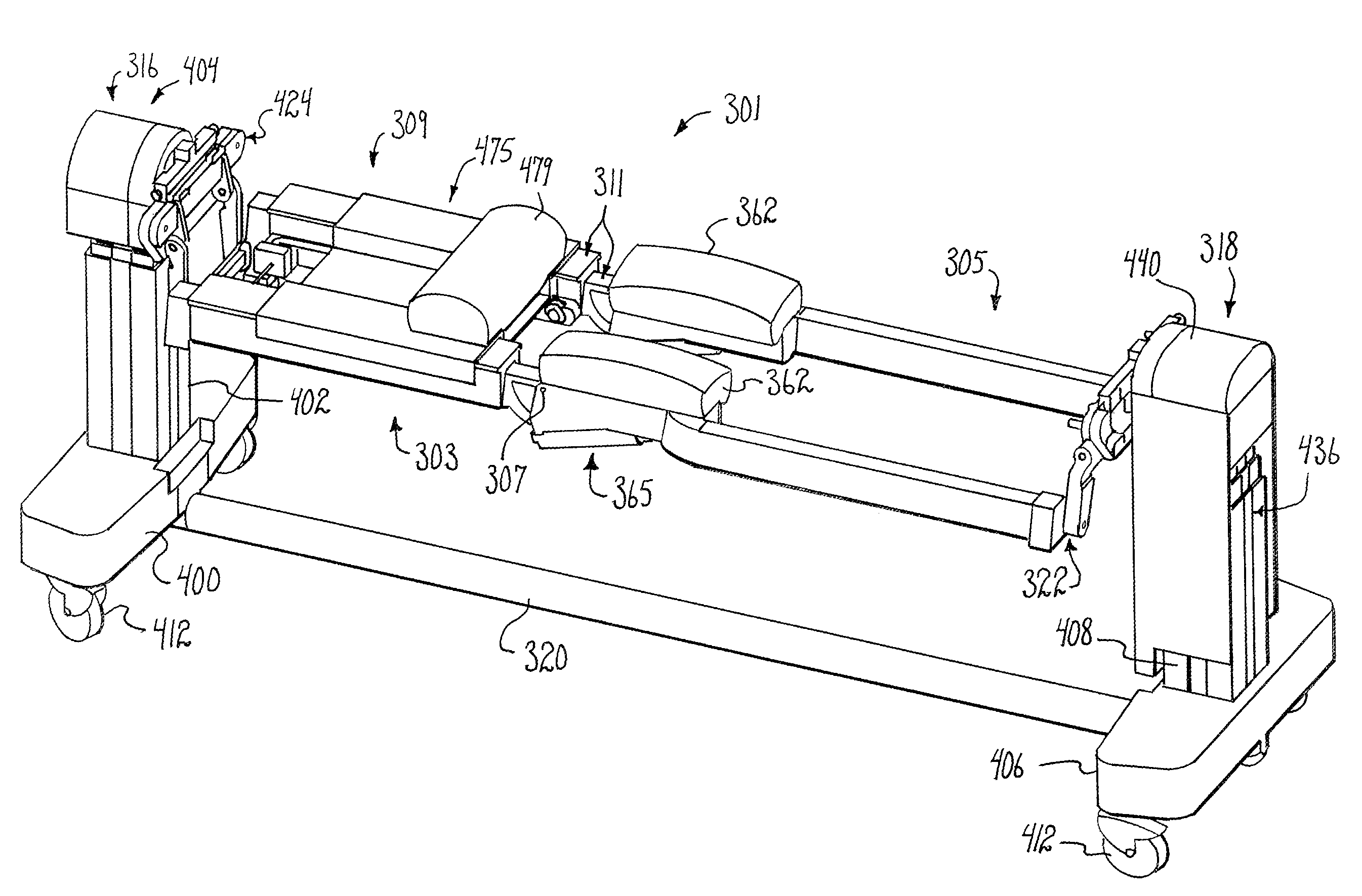
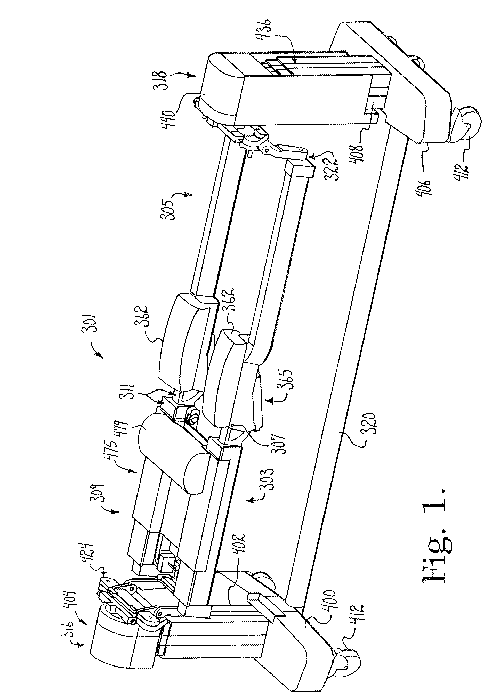
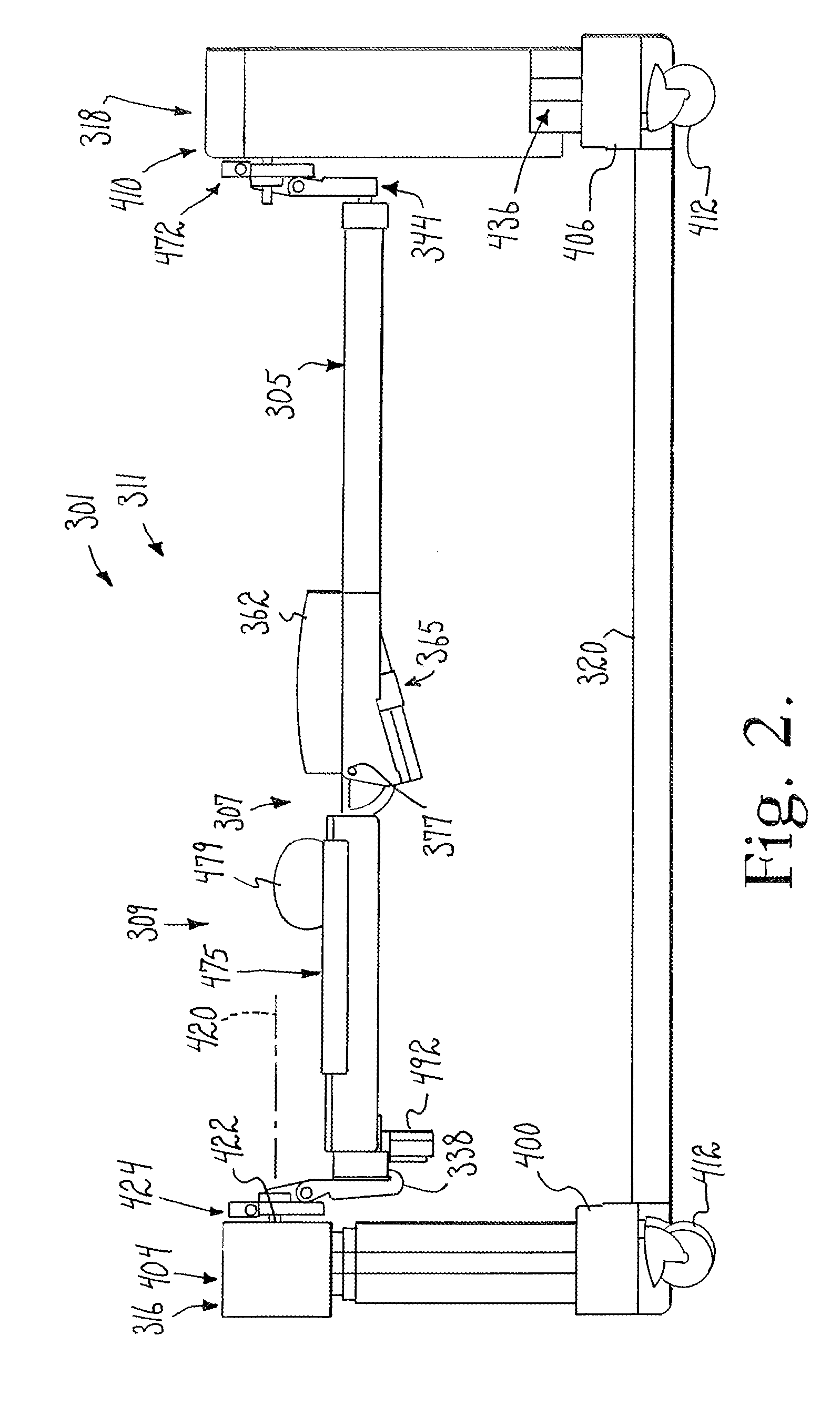
[0083]Referring to the drawings in more detail, the reference number 301 generally designates a patient support structure with a body slide position digitally coordinated with a hinge angle, according to the present invention. The patient support structure 301 generally includes an upper body frame 303 and a lower body frame 305 which are hingedly connected at a support hinge 307 to enable hinged articulation therebetween. A body slide assembly 309 is engaged...


PUM


Abstract

An articulated patient support apparatus includes upper and lower body support frames hinged together to form a patient support assembly which is hinged to head and foot end supports. One end of the assembly includes a length compensator to enable hinged angulation between the body support frames. Hinge motors are connected between the frames to cause hinged articulation therebetween. One or both of the body support frames has a body slide assembly mounted thereon to enable part of a patient's body to move linearly along the particular body support frame by operation of a slide motor to compensate for hinged articulation of the frames. The hinge motors and slide motor have encoders interfaced to a controller to digitally coordinate sliding movement with hinging articulation.

Description

CROSS-REFERENCE TO RELATED APPLICATIONS[0001]This application claims the benefit of U.S. Provisional Application No. 61 / 742,098 filed Aug. 2, 2012; U.S. Provisional Application No. 61 / 743,240 filed Aug. 29, 2012; U.S. Provisional Application No. 61 / 849,035 filed Jan. 17, 2013; U.S. Provisional Application No. 61 / 795,649 filed Oct. 22, 2012; U.S. Provisional Application No. 61 / 849,016 filed Jan. 17, 2013; and U.S. Provisional Application No. 61 / 851,199 filed Mar. 15, 2013, the entirety of which are incorporated by reference herein.[0002]This application is a continuation-in-part of U.S. patent application Ser. No. 13 / 986,060 filed Mar. 14, 2013; which is a continuation-in-part of U.S. patent application Ser. No. 12 / 803,192 filed Jun. 21, 2010; which is a continuation-in-part of U.S. patent application Ser. No. 12 / 288,516 filed Oct. 20, 2008 and now U.S. Pat. No. 7,739,762, and which claimed the benefit of U.S. Provisional Application No. 60 / 960,933 filed Oct. 22, 2007, the entirety o...

Claims


Application Information

Patent Timeline
Patent Type & Authority Applications(United States)
IPC IPC(8): A61G13/08
CPCA61G13/08A61G13/0036A61G13/04A61G13/06A61G13/02A61G13/123A61G13/0054
Inventor JACKSON, ROGER P.
Owner WARSAW ORTHOPEDIC INC
Why Eureka
Try Eureka